Welcome to 4WD expansion board repository
4WD expansion board manual
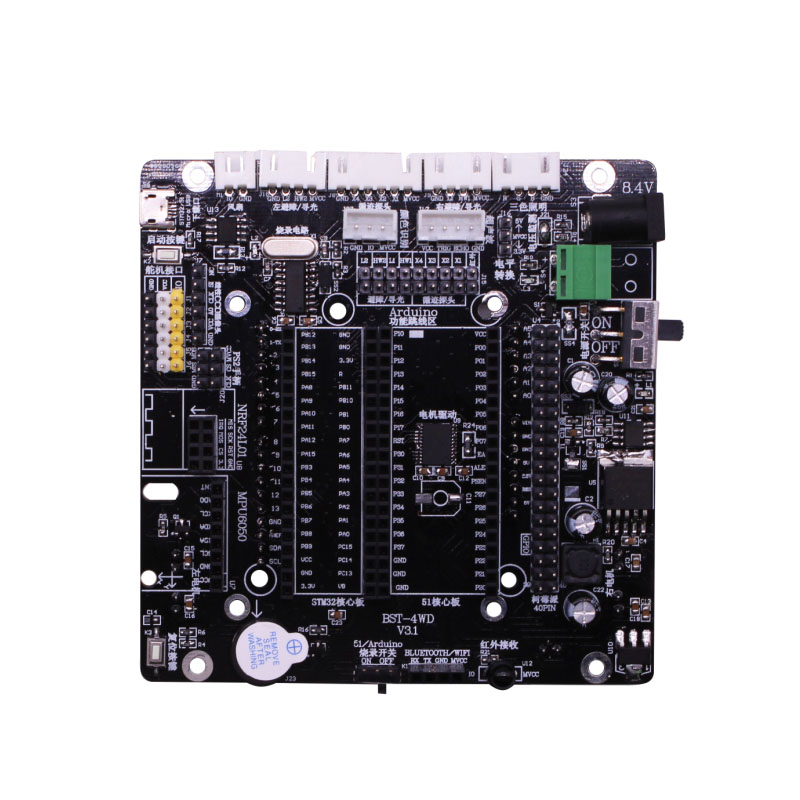
Front:

Back:

1.Fan interface:

1-1 position


1-2 Schematic diagram
The interface has two pins: GND, IO port. When the IO port gets high level, the fan can rotate.
Pin table:

2.Left and right infrared obstacle avoidance (light seeking) interface:

2-1 Position


2-2 Schematic diagram
The interface has four pins: VCC, GND, and two OUT ports. Under normal working conditions, VCC is 5V voltage.We can connect the infrared obstacle avoidance sensor module to these two joints, and judge whether the front is an obstacle by detecting the level of the two OUT1 ports.
Pin table:

Note:When using the Arduino core controller, the corresponding IN5 and in1-t,IN7 and in3-t need to be connected with the jumper cap.

2-3 Position with jumper cap
3. Light seeking (Left and right infrared obstacle avoidance) interface:

3-1 Position


3-2 Schematic diagram
The interface has four pins: VCC, GND, and two OUT ports. Under normal working conditions, VCC is 5V voltage.We can connect the infrared light-seeking sensor module to these two interfaces, and judge whether there is light by detecting the level of the two OUT2 ports.
Pin table:

Note:When using the Arduino core controller, the corresponding IN6 and in2-t,IN8 and in4-t need to be connected with the jumper cap.

3-3 Position with jumper cap
4. 4-Channel tracking interface

4-1 Position


4-2 Schematic diagram
The interface has six pins: VCC, GND, IN1, IN2, IN3, and IN4.VCC is 5V voltage under normal operation.We can connect a four-channel tracking module here, and judge whether it is on the black track by checking the level of IN1, IN2, IN3 and IN4 ports.
Pin table:

Note:When using the Arduino core controller, the corresponding IN1 and in1-t,IN2 and in2-t, IN3 and in3-t, IN4 and in4-t need to be connected with the jumper cap.

4-3 Position with jumper cap
5.RGB LED module interface


5-1 Position


5-2 Schematic diagram
The interface has four pins: GND, LED R, LEDG, LEDB. When the LED R, LED G, and LED B pins are respectively turned on, the corresponding color lights (red, green, and blue) can be lit. When any two of the pins (or three pins) are at a high level, the RGB light will appear in a mixture of two colors (three colors).
Pin table:

6. Ultrasonic module interface

......
For more details, please click "Download" to get.