Welcome to Sound sensor repository
Sound sensor

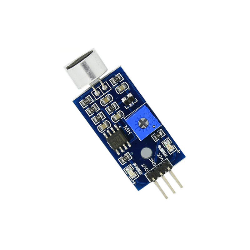
1. Description of Pin

1-1 Position of pin

2. Potentiometer

2-1 Position of Potentiometer
It is necessary to adjust the potentiometer of the sound sensor module to optimize the sensitivity.
3.Power indicator light

3-1 Position of indicator light

3-2 Schematic
This power indicator will illuminate when the module is powered normally.
4.Switch indicator light

4-1 Position of indicator light

4-2 Schematic
When the sound level reaches the set threshold, this indicator will be illuminated, indicating that the module has recognized the sound in the current environment.
5.Sound receiving head

5-1 Position of receiving head

5-2 Schematic
The module receives sound by it, and the sound needs to face the receiver to obtain the best experimental results.
6.MCU

6-1 Position of MCU

This master chip of module.
Hardware connection: (The definition of the pin can be changed in the program by yourself)
1.Connect to Arduino board.

2.Connect to Micro:bit board.

We will provide Arduino, Micro:bit driver source code.