Welcome to Serial communication module repository
1. Test USB-TTL mode
1. Test USB-TTL mode
Before testing, confirm that the serial port driver has been correctly installed and that the computer can correctly recognize the COM port device after plugging in the module.
USB-TTL mode is typically used to convert TTL serial port data into USB data to enable interaction with a computer. Serial port assistant software can be used to view the serial port data content and perform some debugging.
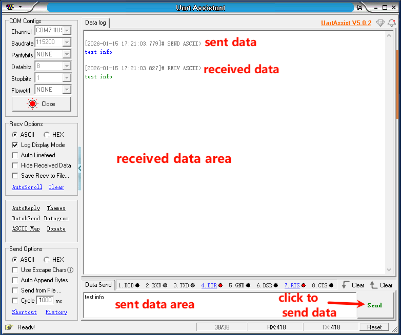
TTL is a full-duplex mode. The TXD and RXD pins of the module can be shorted to perform a data loopback test and verify whether the USB to TTL function is working properly.
Before starting the test, you will need to prepare the following hardware: a Windows computer, a matching USB Type-C data cable, a serial port module, a jumper cap, and a female-to-female DuPont wire.
Below, we will use a Windows computer as an example to demonstrate the steps.
(1)Shorting TXD and RXD can be done by connecting these two pins using a jumper cap or DuPont wire.
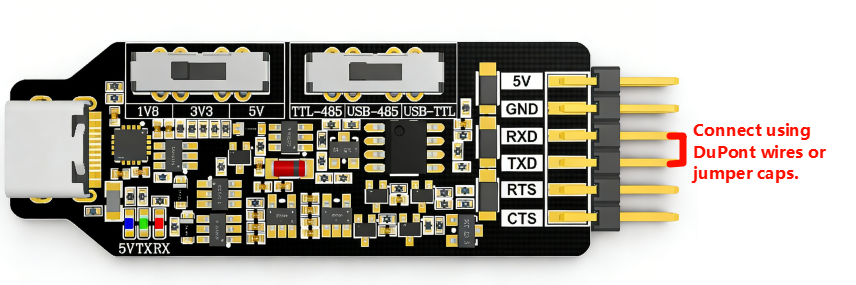
(2)Switch the operating mode selection switch to the right-hand USB-TTL mode.
(3)Connect the module to the computer using a USB Type-C cable.
(4)Open the serial port assistant software (found in Annex -> Serial Port Assistant), and select the module's serial port number.
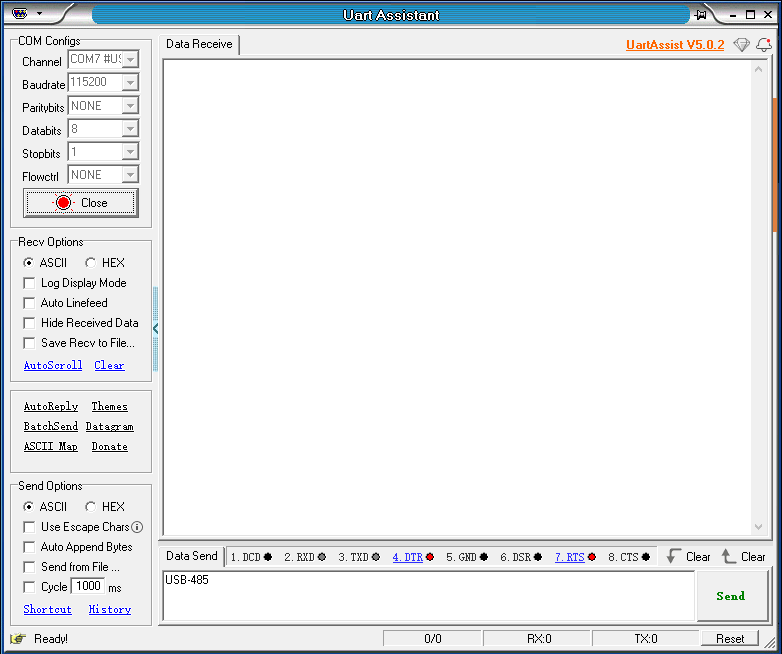
(5)Perform loop closure test
(6)Test CTS pin
Connect the CTS pin to the GND pin using a DuPont wire. You should see the CTS indicator light up in the serial port assistant, indicating that CTS=1, as shown in the image below.
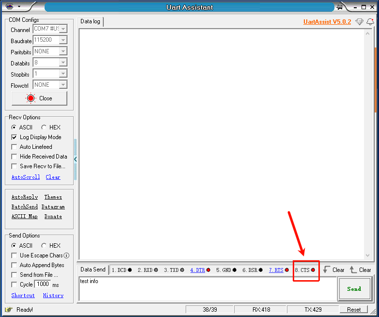
The CTS pin of the module is reversed internally by the CH340 chip. When the CTS pin is connected to GND, CTS=0, and the computer will then display CTS=1. When CTS is connected to VCC (nothing is connected), the computer will display CTS=0.
(7)Test RTS pin
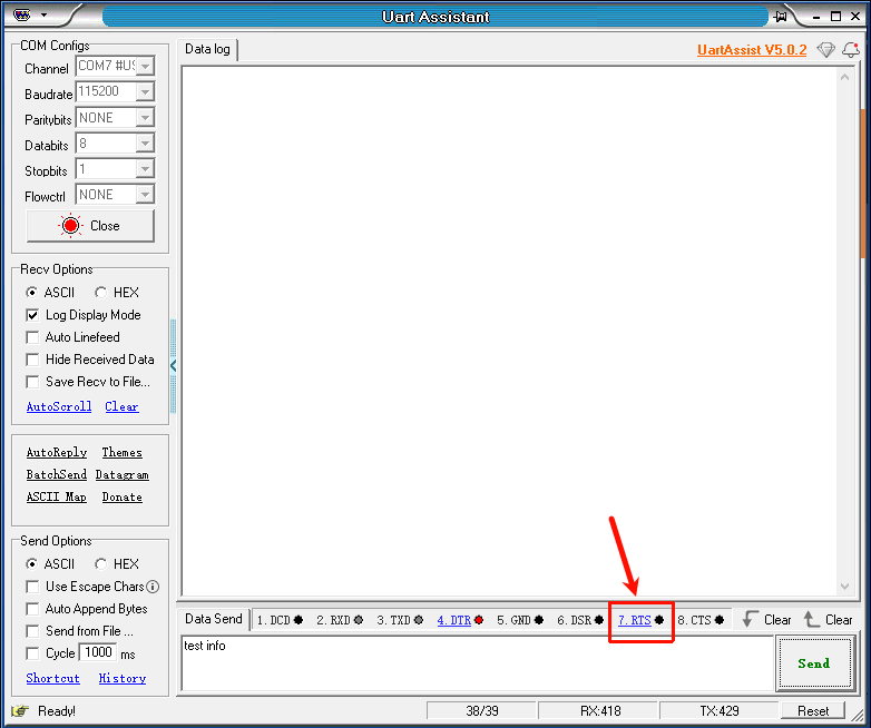
After the CTS test is successful, connect the CTS pin and the RTS pin using DuPont wires. Then, click the RTS button on the serial port assistant. When the red light next to the RTS indicator button is on, the red light next to the CTS button will also be on. When the red light next to the RTS indicator button goes out, the red light next to the CTS button will also go out. (See the image below.)
The above are the testing steps for USB to TTL mode conversion.
Common Motherboard TTL Voltages
| motherboard | TTL voltage |
|---|---|
| STM32 series motherboards | 3.3V |
| MSPM0G3507 | 3.3V |
| Jetson series motherboards | 3.3V |
| Raspberry Pi series motherboards | 3.3V |
When using the above motherboard for serial communication, the TTL voltage selection switch needs to be set to the middle position: 3V3.