Welcome to Serial communication module repository
2. Test USB-RS485 mode
2. Test USB-RS485 mode
Before testing, confirm that the serial port driver has been correctly installed and that the computer can correctly recognize the COM port device after plugging in the module.
USB-RS485 mode is typically used to convert RS485 serial port data into USB data to enable interaction with a computer. Serial port assistant software can be used to view the serial port data content and perform some debugging.
RRS485 is a half-duplex mode and cannot be directly shorted like TTL. Instead, it needs to be tested through another USB-RS485 module.
Before starting the test, you will need to prepare the following hardware: a Windows computer, two matching USB Type-C data cables, two serial port modules, and two female-to-female DuPont wires.
We will use a Windows computer as an example to test the USB-RS485 function. The operation is as follows:
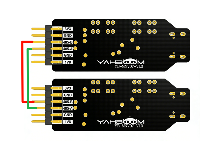
(1)Connect the two modules 485-A/485-B using DuPont wires, i.e., A to A, B to B. (See diagram)
(2)Set the operating mode selection switch to the middle USB-RS485 mode.
(3)Connect the two modules to the computer using a USB Type-C cable.
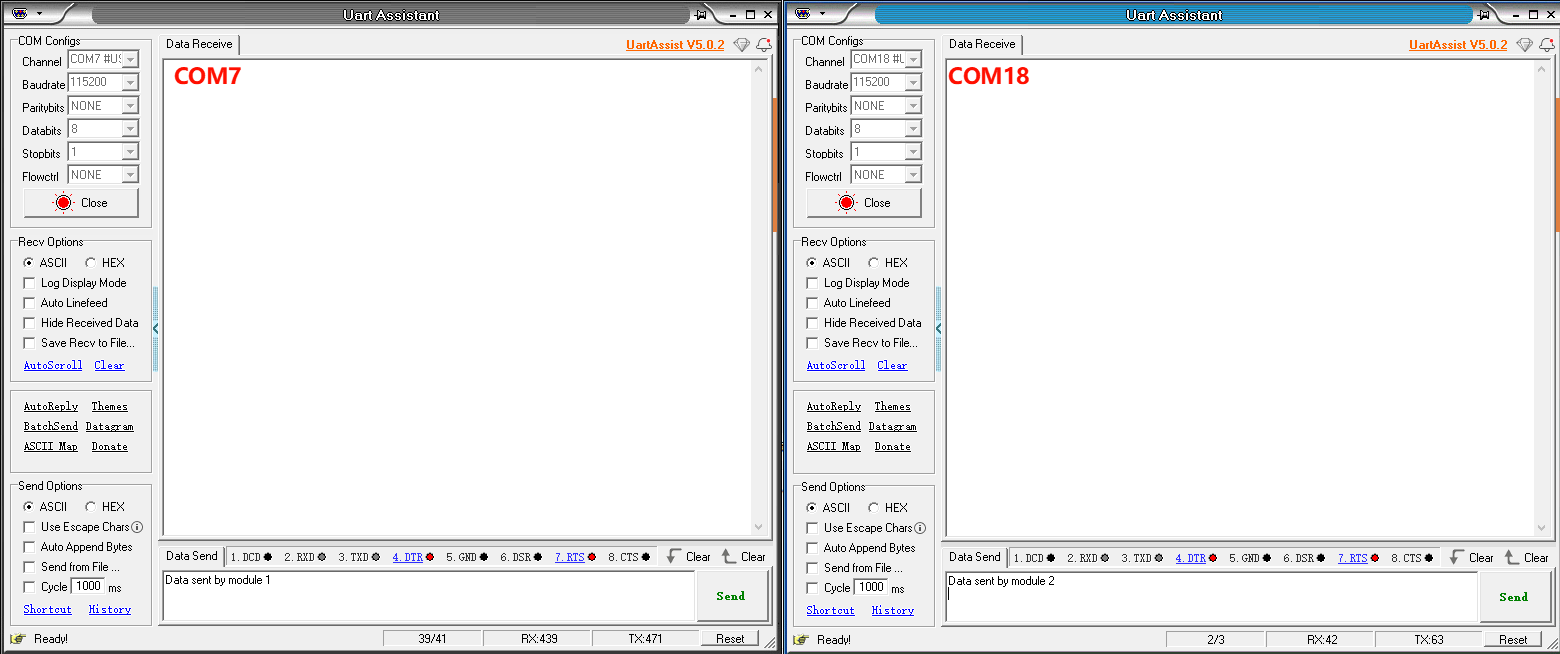
(4)Open the serial port assistant software (found in Annex -> Serial Port Assistant). Open two serial port assistant windows and select the serial port numbers of the two modules respectively. Note that the baud rate, stop bits, data bits, and parity bits must be consistent, as shown in the figure.
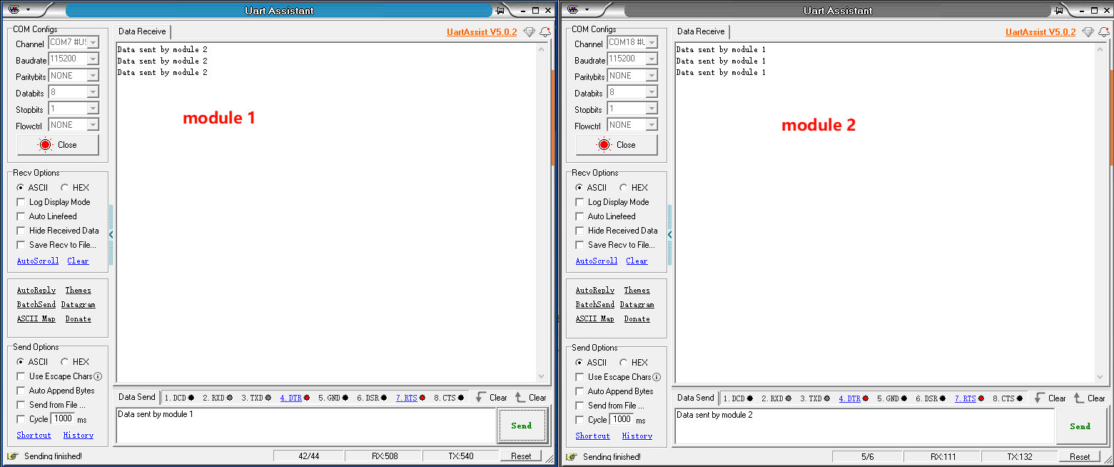
(5)Clicking the send button on COM7 module 1 will cause the TXD indicator light on module 1 to flash, while the RXD indicator light on module 2 will flash. Conversely, clicking the send button on COM18 module 2 will cause the TXD indicator light on module 2 to flash, while the RXD indicator light on module 1 will flash. The results are shown in the image below.
The above are the testing steps for USB to RS485 conversion.