Welcome to 3 color RGB repository
3 color RGB module
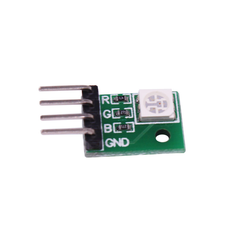
The actual object is shown below.


1.Description of Pin

1-1 Position of Pins
It can be connected by cable or DuPont wire.

2.Lamp bead

Working principle:
3 LEDs (red, green, blue) are packaged in the RGB lamp module. We can mix different colors(256*256*256) by controlling the brightness of the three LEDs.
We will provide Arduino driver source code.
(The definition of the pin can be changed in the program by yourself)
3.Actual object connection diagram:
We need to connect the circuit as shown in the figure below.

4.Experimental code analysis:
int red = 11; //Red light pin of 3 color RGB module is connected to digital port 11 of Arduino UNO
int green=10; //Green light pin of 3 color RGB module is connected to digital port 10 of Arduino UNO
int blue=9; //Blue light pin of 3 color RGB module is connected to digital port 9 of Arduino UNO
int led,val=0,count=0,val_red,val_green,val_blue;
void setup()
{
pinMode(red, OUTPUT);
pinMode(green, OUTPUT);
pinMode(blue, OUTPUT);
}
void led_off()
{
digitalWrite(red,LOW);
digitalWrite(green,LOW);
digitalWrite(blue,LOW);
}
void led_all() //white
{
digitalWrite(red,HIGH);
digitalWrite(green,HIGH);
digitalWrite(blue,HIGH);
}
void loop()
{
led_off();
while(val<255) //The pwm value of red light is added from 0 to 255, the red light is gradually brighter.
{
analogWrite(red, val);
delay(5);
val++;
}
while(val>0) //The pwm value of red light is reduced from 255 to 0, the red light is gradually extinguished.
{
analogWrite(red, val);
delay(5);
val--;
}
led_off();
delay(10);
while(val<255) //The pwm value of green light is added from 0 to 255, the green light is gradually brighter.
{
analogWrite(green, val);
delay(5);
val++;
}
while(val>0) //The pwm value of green light is reduced from 255 to 0, the green light is gradually extinguished.
{
analogWrite(green, val);
delay(5);
val--;
}
led_off();
delay(10);
while(val<255) //The pwm value of blue light is added from 0 to 255, the blue light is gradually brighter.
{
analogWrite(blue, val);
delay(5);
val++;
}
while(val>0) //The pwm value of blue light is reduced from 255 to 0, the blue light is gradually extinguished.
{
analogWrite(blue, val);
delay(5);
val--;
}
led_off();
delay(10);
while(val_blue<255) //Various colors brighten to reach full light to form white light
{
if(val_red<55)
{
analogWrite(red, val_red);
delay(5);
val_red++;
}
else if(val_red<155)
{
analogWrite(red, val_red);
analogWrite(green, val_green);
val_red++;
val_green++;
delay(5);
}
else if(val_red<255)
{
analogWrite(red, val_red);
analogWrite(green, val_green);
analogWrite(blue, val_blue);
val_red++;
val_green++;
val_blue++;
delay(5);
}
else if(val_green<255)
{
analogWrite(red, val_red);
analogWrite(green, val_green);
analogWrite(blue, val_blue);
val_green++;
val_blue++;
delay(5);
}
else if(val_blue<255)
{
analogWrite(red, val_red);
analogWrite(green, val_green);
analogWrite(blue, val_blue);
val_blue++;
delay(5);
}
}
val_red=0;
val_green=0;
val_blue=0;
while(count<10) //Each light flashes separately
{
count++;
led_off();
delay(50);
digitalWrite(red,HIGH); //red
delay(50);
led_off();
delay(50);
digitalWrite(green,HIGH); //green
delay(50);
led_off();
delay(50);
digitalWrite(blue,HIGH); //blue
delay(50);
led_off();
delay(50);
led_all();//white
delay(50);
led_off();
delay(50);
}
count=0;
led_off();
delay(200);
digitalWrite(red,HIGH); //red
delay(200);
led_off();
delay(200);
digitalWrite(green,HIGH); //green
delay(200);
led_off();
delay(200);
digitalWrite(blue,HIGH); //blue
delay(200);
led_off();
delay(200);
led_all();//white
delay(200);
led_off();
delay(200);
}
5.Experimental steps:
1. We need to open the program for this experiment:
code-3_color_RGB_module.ino, click “√”under the menu bar,compile the program, and wait for the words of Done compiling in the lower left corner, as shown in the following figure.

2. In the menu bar of Arduino IDE,you need to select the 【Tools】---【Port】--- select the port that the serial number displayed by the device manager just now.for example:COM6,as shown in the following figure.


3. After the selection is completed, you need to click “→”under the menu bar,and upload the program to the Arduino UNO board, when appears to Done uploading on the lower left corner , that means that the program has been successfully uploaded to the Arduino UNO board, as shown in the following figure.

4. After the program upload is completed, we can see that the three-color lamp module will light the different colors according to the code, as shown in the figure below. In addition, you can set the color and delay time of the lamp in the code.