Welcome to 24-channel Servo Drive Board repository
Download program
Download program
Download programPreliminary preparationhardwaresoftwareBurning program24-channel steering gear control boardconnectFlyMcu configurationVerification programDebugging/communication serial port baud rateProtocol
Tutorial demonstrates how to program the 24-channel servo control board: serial port programming program.
Preliminary preparation
hardware
Control Board: 24-channel steering gear control board
Data cable: Type-C data cable
software
Serial port burning software: FlyMcu
Program source code: ***.hex (this suffix file is the program file required for serial port burning)
xxxxxxxxxxYou can search the burned program files in the information by yourself!
Burning program
24-channel steering gear control board
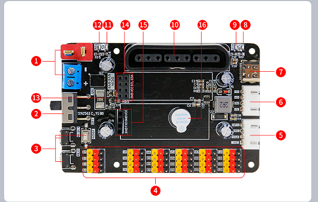
When the power supply voltage of the 24-channel servo control board does not reach the programmed voltage (6.5V), a low voltage alarm will occur. This is a normal phenomenon!
xxxxxxxxxxThe voltage set by the program is set based on the external battery pack, so power supply through the Type-C interface will be lower than this voltage!But we can judge whether there is a program on the 24-channel servo control board through this alarm sound.
connect
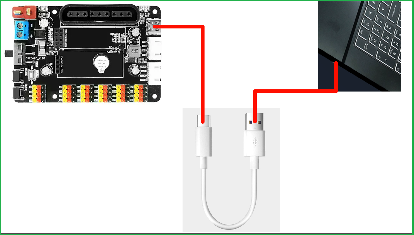
| Type-C data cable | Equipment |
|---|---|
| Type-C interface | 24-channel servo control board |
| USB interface | Computer |
Note: The burning program needs to press and hold the BOOT button on the 24-channel servo control board to connect to the computer!
FlyMcu configuration
Except for the serial port number recognized by your own system (in my case it is COM8), check other options as shown below, and finally click "Start Programming"!
xxxxxxxxxxNote: You need to press and hold the BOOT button before connecting the 24-channel servo control board!
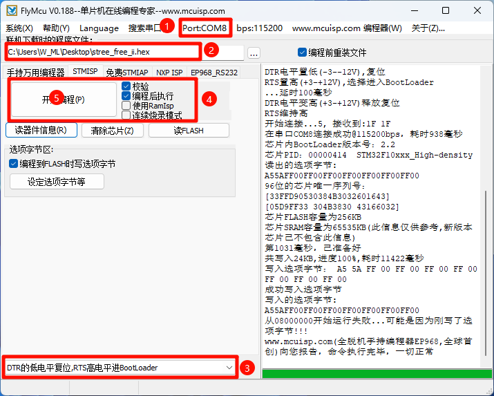
If the 24-channel servo control board is not powered through the T-shaped interface, the servo control board will emit a continuous buzzer after the program is burned!
Verification program
What data is sent through the serial port will be printed:
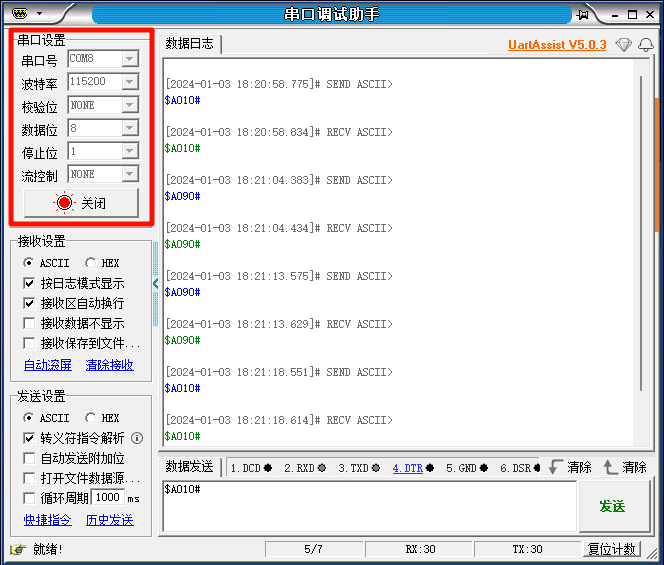
If an external 7.4V power supply is connected, the servos on the 24-channel servo control board can be controlled according to the following communication protocol!
Debugging/communication serial port baud rate
| Device | Baud Rate |
|---|---|
| PC | 115200 (Type-C interface: USART1) |
| Host computer | 9600 (PH2.0 4Pin interface: USART3) |
| Bluetooth | 9600 (Bluetooth interface: UART5) |
Protocol
The serial port communication baud rate is based on the parameters in the table above. Different interfaces use different baud rates.
| Data header | Servo number | Servo angle | Data tail |
|---|---|---|---|
| $ | A-P | 0-180 | # |
xxxxxxxxxxExample:Servo 1 turns to an angle of 10 degrees: $A010#