Welcome to 8-channel Grayscale Tracking Module repository
4.ESP32
Data Reading
Data Reading1. Quick Start2. Hardware Wiring3. Usage Method4. Phenomenon and Results5. Code Explanation
1. Quick Start
This tutorial explains how to use the ESP32-S3 motherboard to read the digital information from an eight-channel grayscale line-following module and print the results via a serial port assistant.
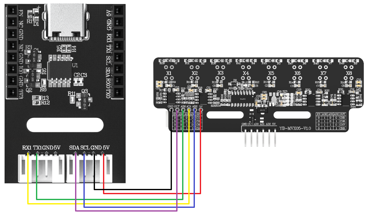
The hardware used in this tutorial is the ESP32-S3 WIFI image transmission module lite and the eight-channel grayscale line-following module sold by Yabo. After connecting the wires according to the wiring diagram below, you can obtain the data by programming the ESP32-S3. Modules other than Yabo's are for reference only.
2. Hardware Wiring
The ESP32-S3's USB port needs to be connected to the computer's USB port using a data cable.
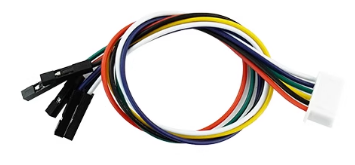
The eight-channel grayscale module sold by Yabo uses XH2.54 to 6-pin DuPont cable for connection:
| Eight-channel grayscale line-following module | ESP32-S3 |
|---|---|
| 5V | 5V |
| GND | GND |
| AD0 | RX1(35) |
| AD1 | TX1(36) |
| AD2 | SCL(37) |
| OUT | SDA(38) |
The serial port and IIC identifiers here are merely labels used on the ESP32 module board; the serial port and IIC functions are not actually used.
3. Usage Method
- Open the programming tool
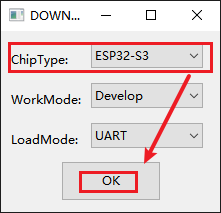
flash_download_tool, select the ESP32-S3 chip, and then click OK.
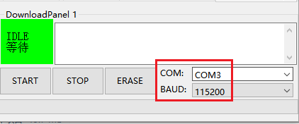
- Connect the ESP32-S3 to the computer via a data cable, and then select the COM port and baud rate in the software.
- In the
SPIDownloadwindow, select three ESP32S3 firmware files to be burned. The path is usually in thebuildfolder under the root directory of the code project. The format is a .bin file. Remember to enter the firmware address. Make sure the box to the left of ".bin file" is checked, and both the file name and address are green.
Check "DoNotChgBin". Leave other configurations as default.
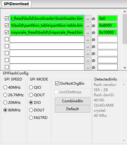
The file and address mapping is shown in the table below:
| Firmware Name | Firmware Address | Remarks |
|---|---|---|
| bootloader.bin | 0x0000 | Boot file |
| partition-table.bin | 0x8000 | Partition table file |
| Grayscale_Read.bin | 0x10000 | Function file |
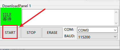
- Click the START button, and the tool will automatically begin flashing the firmware.
Note: If flashing the firmware does not start automatically, please press and hold the IO0 key, then press the EN key, and release them simultaneously to manually enter flashing mode, and then click the START button.
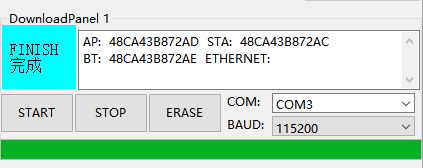
- After downloading, a blue FINISH indicator will appear. At this point, power off and restart the microcontroller or press the EN key to restart the program and close the programming tool. Finally, use a serial port assistant to open this port to see the printed information.
4. Phenomenon and Results
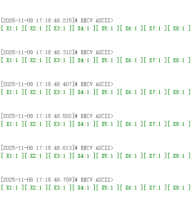
After programming, open the serial port assistant. You can see the continuously printed digital values of the eight-channel grayscale tracking module. X1 corresponds to X1 on the module; when the X1 LED is lit, the corresponding value is 1.
5. Code Explanation
x
// Grayscale_Read.cvoid app_main(void){ Grayscale_Sensor_Init(); xTaskCreate( Grayscale_ReadData_Task, // Task function "GrayscaleReadData", // Task name 4096, // Stack size (bytes) NULL, 2, // Priority NULL );}void Grayscale_ReadData_Task(void *arg) { while (1) { Grayscale_Sensor_Read_All(g_sensor_data); for (i = 0; i < GRAYSCALE_SENSOR_CHANNELS; i++) { printf("[ %s:%d ]", sensor_labels[i], g_sensor_data[i]); } printf("\n"); delay_ms(100); }}app_main: The main entry point function for the ESP-IDF project. It first callsGrayscale_Sensor_Init()to initialize the sensor, and then usesxTaskCreate()to create a FreeRTOS task specifically for reading and printing sensor data.Grayscale_ReadData_Task: An infinite loop task. In each loop, it callsGrayscale_Sensor_Read_All()to retrieve the latest sensor data, and then formats and outputs the data to the serial port usingprintf.
x
// grayscale_sensor.cvoid Grayscale_Sensor_Init(void){ gpio_config_t io_conf_output = { .pin_bit_mask = (1ULL << 35) | (1ULL << 36) | (1ULL << 37), .mode = GPIO_MODE_OUTPUT, //... }; gpio_config(&io_conf_output); gpio_config_t io_conf_input = { .pin_bit_mask = (1ULL << 38), .mode = GPIO_MODE_INPUT, //... }; gpio_config(&io_conf_input);}void Grayscale_Sensor_Read_All(uint16_t* sensor_values){ uint8_t i; for (i = 0; i < GRAYSCALE_SENSOR_CHANNELS; i++) { _select_channel(i); _delay_us(50); sensor_values[i] = Read_OUT_value(); }}Grayscale_Sensor_Init: Initializes GPIOs using thegpio_configstructure and functions provided by ESP-IDF. Configures control pins (GPIO35-37) as outputs and data pins (GPIO38) as inputs.Grayscale_Sensor_Read_All: Iterates through all 8 sensor channels, selects a channel using_select_channel, reads its value, and stores it in an array.