Welcome to 8-channel Grayscale Tracking Module repository
1. MSPM0 Smart Car
Eight-channel grayscale moduleHardware WiringPartial Code AnalysisMain FunctionsExperimental Phenomena
Eight-channel grayscale module
Our store offers four types of eight-channel grayscale modules: distinguished by light color, namely: Red, Green, Blue, White. Different colored grayscale modules are suitable for different line inspection scenarios. The provided source code is applicable to all sensors.
| Sensor Classification | Red | Green | Blue | White |
|---|---|---|---|---|
| White background | Green, Cyan, Blue, Black | Red, Blue, Purple, Black | Yellow, Red, Green, Black | Black |
| Black background | Red, Orange, Yellow, White | Green, Yellow, Cyan, White | Blue, Purple, Cyan, White | White |
Hardware Wiring
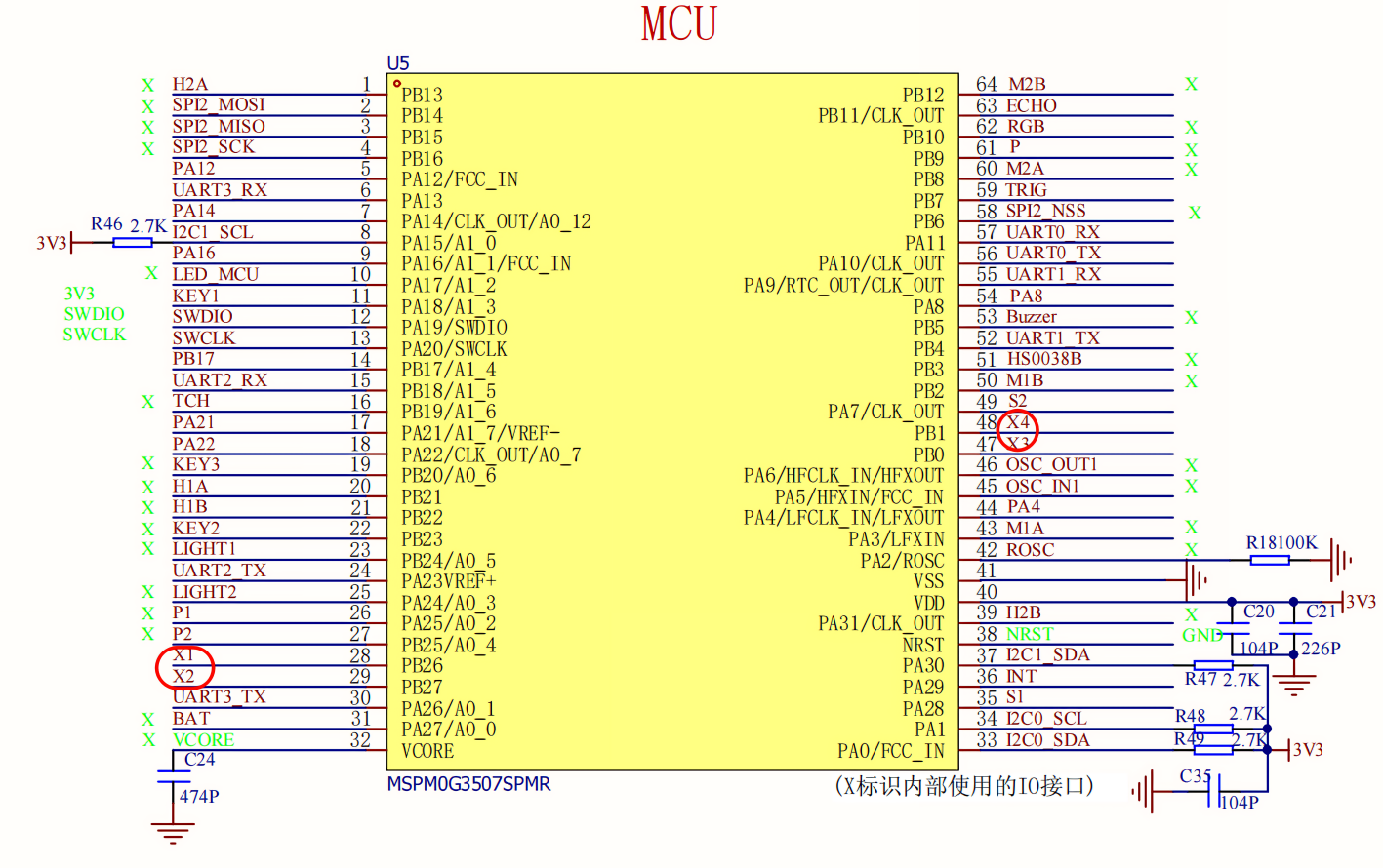
| Eight-channel grayscale module | MSPM0G3507 |
|---|---|
| 5V | 5V |
| GND | GND |
| AD2 | X1 |
| AD1 | X2 |
| AD0 | X3 |
| OUT | X4 |

Partial Code Analysis
Control Principle
Modify the effective level by changing ACTIVE_VALUE to 0/1
bsp_ir_eight.c
x
/*** @brief Read the status of eight infrared sensors* @param ir_results An array of length 8, used to store the status (0/1) of each channel*/ void ReadEightIR(uint8_t ir_results[8]) { for (int channel = 0; channel < 8; channel++) { // Calculate the C, B, and A values corresponding to the current channel (C is the most significant bit, A is the least significant bit) uint8_t c = (channel >> 2) & 0x01; uint8_t b = (channel >> 1) & 0x01; uint8_t a = channel & 0x01; SET_CHANNEL(c, b, a); // Set the channel selection pin //This delay time can be adjusted to a stable state delay_us(100); // Read the infrared status of the current channel and store it in the result array ir_results[channel] = READ_IR_OUT() ? 1 : 0; }}bsp_ir_eight.h
x
// Port// Channel selection: A (least significant bit)// Channel selection: B// Channel selection: C (most significant bit)// Infrared detection output pin// Set the level (0 or 1) of channel selection pins C, B, and A Main Functions
ReadEightIR
| Function Prototype | void ReadEightIR(uint8_t ir_results[8]) |
|---|---|
| Function Description | Reads the status of eight infrared sensors and stores the status (0 or 1) of each channel into a specified array. Channel selection is achieved by calculating the corresponding C, B, and A values. The status is read and stored after a 1ms delay. |
| Input Parameters | ir_results: An 8-byte uint8_t array used to store the status of the eight infrared sensors (0 indicates no detection, 1 indicates detection). |
| Return Value | None |
Experimental Phenomena
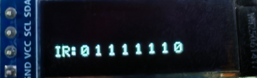
After connecting the car to the OLED module and programming the MSPM0, place the car on the map. The car will automatically start tracking, and the sensor data will be displayed on the OLED. Due to differences in motor parameters and ground material, if the tracking effect is poor, the parameters need to be adjusted manually.