Welcome to 8-channel Grayscale Tracking Module repository
6. Raspberry Pi Pico
Data Reading
Data Reading1. Quick Start2. Hardware Wiring3. Usage Method4. Phenomenon and Results5. Code Explanation
1. Quick Start
This tutorial explains how to use the PICO2 motherboard to read the digital information from an eight-channel grayscale tracking module and view the print results through the Shell window.
The hardware used in this tutorial is the PICO2 and eight-channel grayscale tracking module sold by Yabo. Refer to the wiring diagram below to connect the wires, then program the PICO2 to obtain the data. Modules other than Yabo's are for reference only.
2. Hardware Wiring
The PICO2's microUSB port requires a microUSB cable to connect to the USB port.
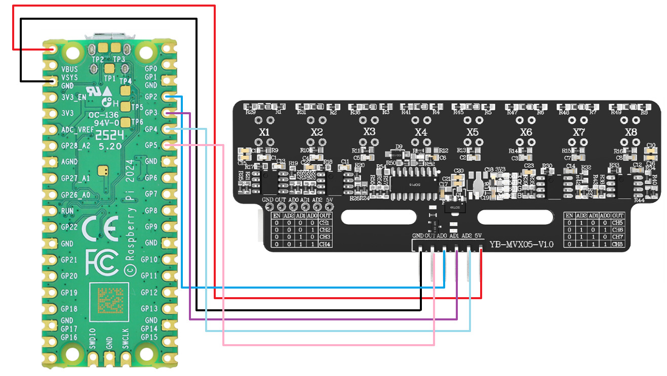
| Eight-channel grayscale tracking module | PICO2 |
|---|---|
| 5V | VBUS |
| GND | GND |
| AD0 | GP2 |
| AD1 | GP3 |
| AD2 | GP4 |
| OUT | GP5 |
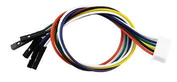
The standard cable for the eight-channel grayscale line-following module sold by Yabo is an XH2.54 to 6-pin DuPont cable. One end of the XH2.54 ribbon cable should be connected to the eight-channel grayscale module, and the other end of the DuPont cable can be connected normally as shown in the picture above:
3. Usage Method
Find the code Grayscale_Read After opening the Thonny software and connecting the Raspberry Pi pico2, click the stop button on the far right of the top toolbar:

Then you can see the current firmware information of pico2 pop up in the message bar at the bottom, which means that the software has recognized the serial port:

If the message bar here shows that the serial port cannot be recognized, or if you are not familiar with basic operations, you need to consult the PICO2 motherboard documentation, find the tutorial on setting up the development environment (Python), and learn the relevant basic usage and firmware flashing. Flashing the firmware to the motherboard will enable serial port recognition:

After successfully recognizing the serial port and printing firmware information, click the green button to start running the script:

4. Phenomenon and Results
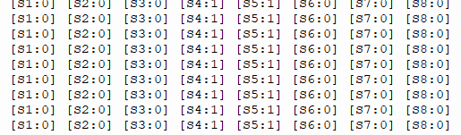
After running the program in Thonny, you can see that the Shell window at the bottom continuously prints the digital values of the eight-channel grayscale tracking module. S1 corresponds to X1 on the module. When the X1 light is on, the value of S1 is 1.
5. Code Explanation
xxxxxxxxxxdef _select_channel(self, channel): """ Select the sensor channel """ self.ad0.value((channel >> 0) & 0x01) self.ad1.value((channel >> 1) & 0x01) self.ad2.value((channel >> 2) & 0x01)def _read_out_value(self): """ Read the value from the OUT pin """ return self.sensor_out.value()def read_all(self): """ Read all channels """ values = [] for i in range(self.channels): self._select_channel(i) time.sleep_us(50) values.append(self._read_out_value()) return valuesdef read_single(self, channel): """ Read a single channel """ if channel >= self.channels: return 0 self._select_channel(channel) time.sleep_us(50) return self._read_out_value()def print_values(self): """ Print all sensor values """ values = self.read_all() for i, value in enumerate(values): print(f"[S{i+1}:{value}]", end=" ") print()_select_channel: Selects the corresponding sensor channel via a control pin based on the passed channel number._read_out_value: Reads the digital output value of the currently selected sensor channel.read_all: Iterates through and reads the current status of all 8 sensor channels.read_single: Reads the current status of a single, specified sensor channel.print_values: Retrieves the sensor values for all channels and prints them in format to the console.