Welcome to STM32F103C8T6 core board repository
3.1. Turn on the LED lights
3.1.Light up the LED lights
1. Learning Objectives
1.Understand the basic use of STM32 microcontroller pins.
2.Learn how to control the onboard LED lights.
2. Hardware construction
This course does not require additional hardware equipment to directly use the on-board LED lights on the STM32 board.
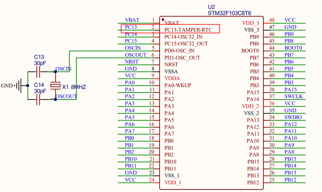
STM32 main control schematic diagram
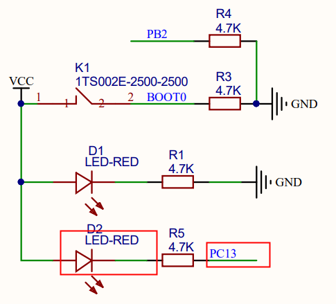
Schematic diagram of LED part
3. Program code analysis
Note: For the GPIO peripheral operation of STM32 in this chapter, the stm32f10x_gpio.c and stm32f10x_rcc.c files need to be added to the project. The functions for GPIO operations are all in stm32f10x_gpio.c, and stm32f10x_gpio.h is the declaration of the function and the macro of some option configurations definition. This has been added in the project template. In the later experiments, we will no longer emphasize the files that have been called by the project template. It is also necessary to include the path of the led file under the newly created APP in KEIL5.
We need to complete the LED driver, so create a led.c and led.h file on the project template and store them in the led folder. The contents of these two files are what we need to write, not library files. Usually the xxx.c file is used to store the written driver, and the xxx.h file is used to store the stm32 header file, pin definition, global variable declaration, function declaration, etc. in xxx.c, and the subsequent code will no longer be declared.
It can be seen from the schematic diagram that there is an LED on the STM32 motherboard connected to the STM32F103 chip pin PC13. If you want to turn on the LED light, you only need to control the PC13 pin to output a low level; if you want to turn off the LED light, you only need to control the PC13 to output a high level
led.c file code:
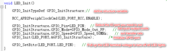
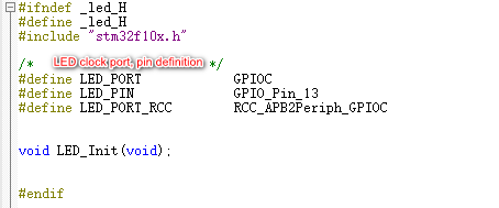
led.h file code:
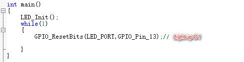
The main function main.c file code is as follows:
4. Experimental phenomenon
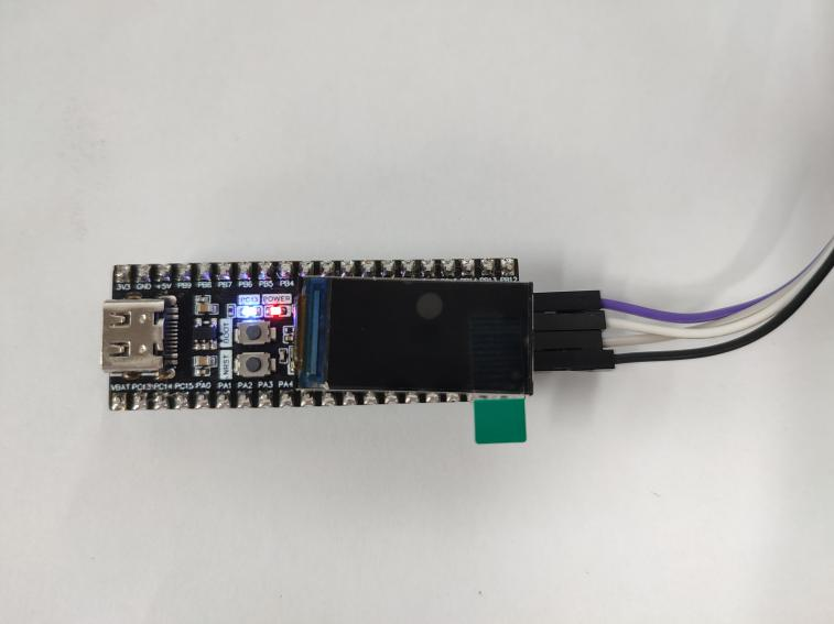
After the program download is complete, we can see that the LED on the PC13 pin of the STM32 motherboard is lit.