Welcome to STM32F103C8T6 core board repository
3.4. ADC acquisition experiment
3.4.ADC acquisition
1. learning target
1.Understand the basics of ADC.
2.Learn the basic use of ADC, and display the collected values on the serial port assistant.
ADC introduction of STM32F1:
ADC (analog to digital converter) is an analog-to-digital converter, which can convert analog signals into digital signals. According to its conversion principle, it is mainly divided into three types: successive approximation type, double integral type, and voltage-frequency conversion type.
STM32 has 1~3 ADCs (STM32F101/102 series has only 1 ADC), these ADCs can be used independently or in dual mode (increased sampling rate). The ADC of STM32 is a 12-bit successive approximation analog-to-digital converter. It has 18 channels and can measure 16 external and 2 internal sources. A/D conversion for each channel can be performed in one-shot, continuous, sweep or intermittent mode. The ADC result can be stored in the 16-bit data registers either left-justified or right-justified. An analog watchdog feature allows the application to detect if the input voltage exceeds user-defined high/low thresholds.
The STM32F103 series has at least 2 ADCs, and the STM32F103C8T6 we chose contains 2 12-bit ADCs. The maximum conversion rate of the STM32 ADC is 1Mhz, that is, the conversion time is 1us (obtained under ADCCLK=14M, the sampling period is 1.5 ADC clocks), do not let the ADC clock exceed 14M, otherwise the accuracy of the result will be reduced. The ADC of STM32 only performs one conversion in single conversion mode. This mode can be started by the ADON bit of the ADC_CR2 register (only applicable to regular channels), or it can be started by an external trigger (applicable to regular channels and injection channels). Yes CONT bit is 0. Taking the regular channel as an example, once the selected channel conversion is completed, the conversion result will be stored in the ADC_DR register, the EOC (end of conversion) flag will be set, and if EOCIE is set, an interrupt will be generated. The ADC will then stop until the next start.
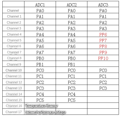
The STM32 ADC channel and GPIO correspondence table is as follows:
2. Hardware wiring construction
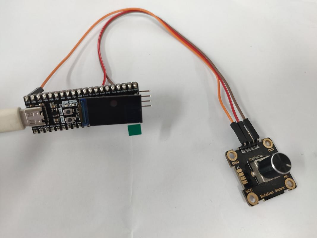
The potentiometer module and DuPont line used in the ADC acquisition experiment need to be purchased separately, otherwise the course cannot be completed due to the lack of important accessories.
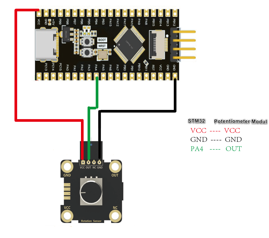
Module Wiring Diagram
3、Program code analysis
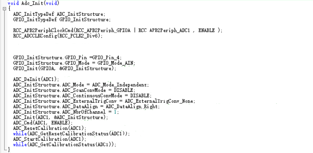
ADC initialization code:
Get the value of ADC:
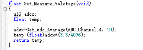
Obtain multiple ADC averages:
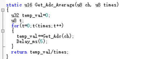
Get actual voltage:
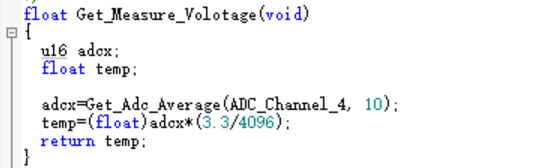
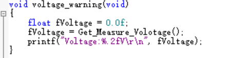
display actual voltage:
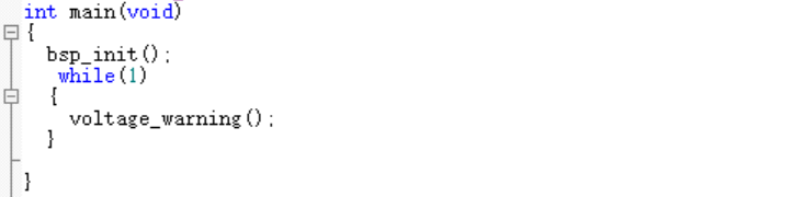
main function:
4.Experimental phenomena
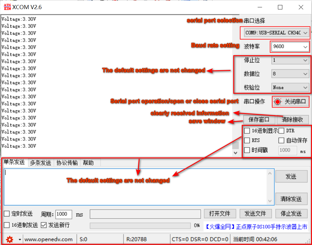
After the program download is complete, configure the serial port assistant as shown in the figure below, adjust the potentiometer knob, and you can see the real-time effect of the voltage changing between 0-3.3v in the serial port assistant receiving window.