Welcome to 2.4G 10-channel Controller repository
PWM receiver usage process
PWM receiver usage process
PWM receiver usage processHardware PreparationHT-10A Remote ControllerPWM ReceiverPairing StepsControlling the PWM Servo
Hardware Preparation
- HT-10A Remote Controller
- PWM Receiver
- PWM Servo: 180°
HT-10A Remote Controller
Install 4 AA batteries in advance to power the HT-10A remote controller:
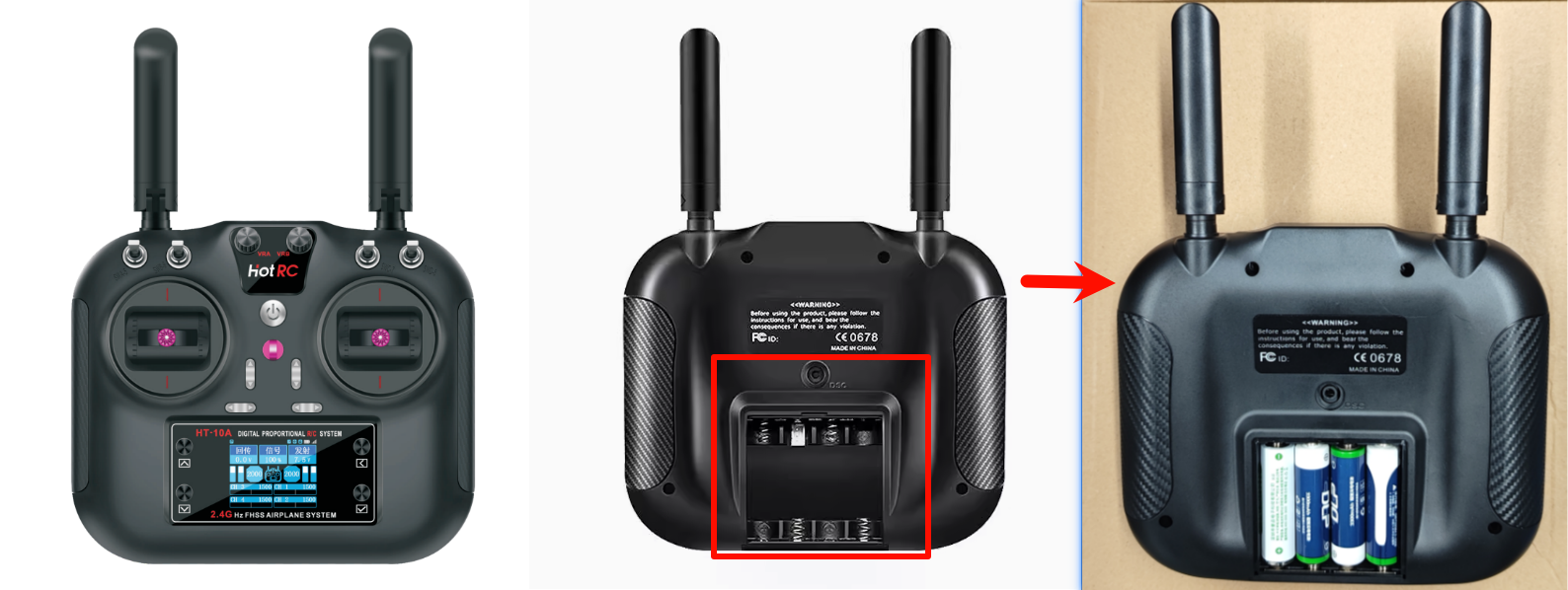
| HT-10A Remote Controller | Default Channels: No channel mapping on the remote |
|---|---|
| CH1 | Right Joystick: Left/Right |
| CH2 | Right Joystick: Up/Down |
| CH3 | Left Joystick: Up/Down |
| CH4 | Left Joystick: Left/Right |
| CH5 | SWA Channel |
| CH6 | SWB Channel |
| CH7 | SWC Channel |
| CH8 | SWD Channel |
| CH9 | VRA Channel |
| CH10 | VRB Channel |
PWM Receiver
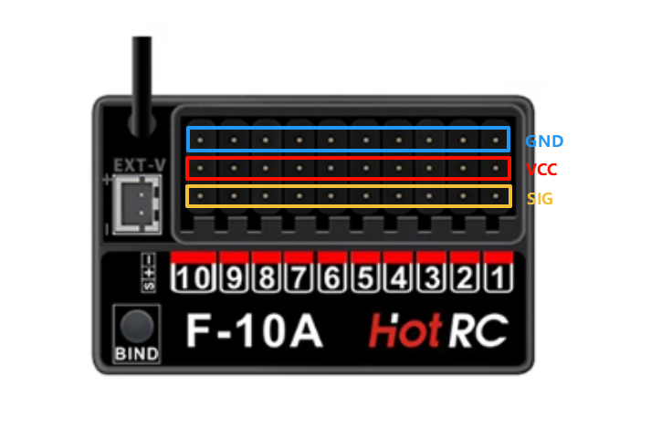
Diagram showing the connection between the PWM receiver and the 180° PWM servo: Users can use other devices to provide 5V power to the PWM receiver
| PWM Receiver | 180° Servo | ROS Control Board (Power for PWM Receiver) |
|---|---|---|
| S (Signal) | SIG (Yellow) | |
| + (Positive) | VCC (Red) | 5V |
| - (Negative) | GND (Brown) | GND |
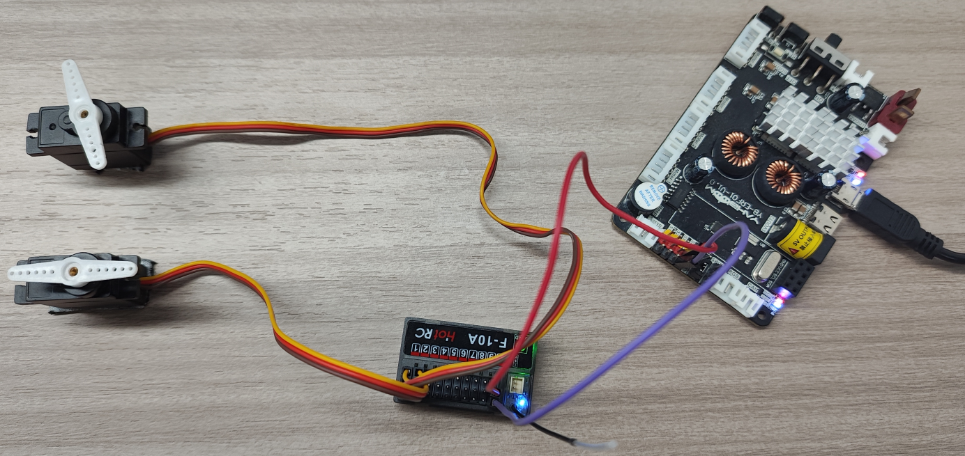
The two 180° PWM servos in the image are connected to CH1 and CH2 respectively. The ROS control board powers the PWM receiver through CH10's VCC and GND!
Pairing Steps
Use a 12V T-type battery pack or MicroUSB cable to power the ROS control board. The ROS control board powers the PWM receiver through the VCC (5V) and GND interfaces.
| PWM Receiver LED Status | Meaning |
|---|---|
| LED Slow Flash | Device not connected |
| LED Fast Flash | Pairing mode |
| LED Solid On | Device connected |
- Power on the PWM receiver. The LED on the PWM receiver will be in slow flash mode;
- Press and hold the button on the PWM receiver for 1 second. The LED will fast flash, indicating the PWM receiver has entered pairing mode;
- Turn on the HT-10A remote controller's power switch. The HT-10A remote controller will automatically pair with the PWM receiver;
- After successful pairing, the LED on the PWM receiver will be solid on: When connected, it cannot enter pairing mode.
Note: The HT-10A remote controller and PWM receiver only need to be paired once. They will automatically connect on next power-on. No need to pair again!
Controlling the PWM Servo
The HT-10A remote controller can set the servo frequency and rotation angle through the display screen and its surrounding buttons:
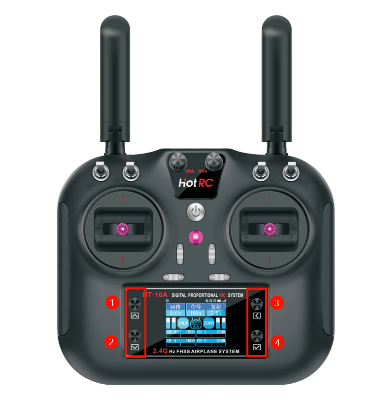
| HT-10A Remote Controller | Function |
|---|---|
| ① | Up Button |
| ② | Down Button |
| ③ | Back Button |
| ④ | OK Button |
On the main interface, press the "OK button" to enter settings, then use the "Up button", "Down button", "Back button", and "OK button" to navigate different options. The tutorial controls a 180° PWM servo:
Recommended settings: Servo frequency: 50Hz, Servo angle: 180°
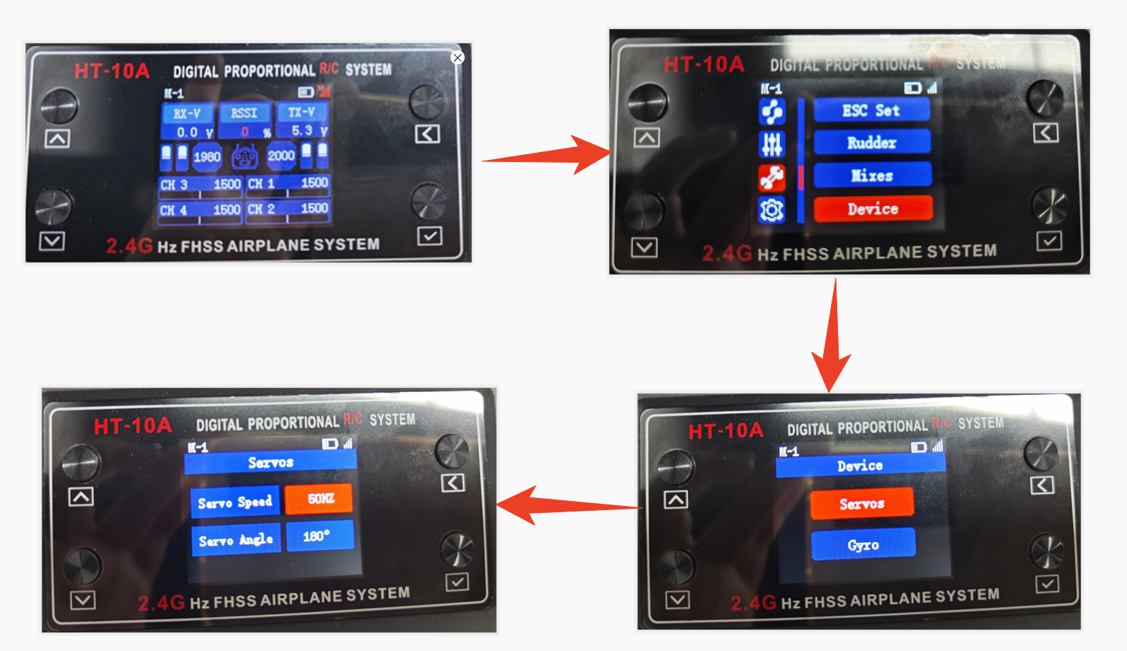
After completing the above settings, you can control the servo on the corresponding channel using the joystick!