Welcome to 2DOF PTZ repository
2. PTZ color tracking
Color Tracking
1. Introduction
Please read the information in the 24-way Servo Driver Board and STM32 Getting Started Tutorial first to understand how to burn programs and the basics of getting started with STM32. This will make it easier to learn and burn the following programs.
2. Equipment list
3. Placement

The placement is as shown in the figure. You can choose our aluminum base frame as the base plate to fix the k230 and the gimbal, or you can choose a fixed base plate. The chassis can be glued to prevent the gimbal from moving too much and causing deviation. The k230 is fixed on the two-dimensional gimbal. When using the battery, if the gimbal rotates too much, you can moderately reduce the pid parameter.
4. Experimental preparation
First, build the 2D gimbal according to the 2D gimbal installation tutorial
Hardware wiring:

| 2D gimbal | 24-way servo driver board |
|---|---|
| X-axis servo | S1 |
| Y-axis servo | S2 |
| K230 vision module | 24-way motor driver board |
|---|---|
| 5V | 5V |
| GND | GND |
| TX | RX3 |
| RX | TX3 |
Note: When plugging in the servo cable, be sure to align the yellow cable with the yellow GPIO port of the 24-way servo driver board, and the brown cable with the black GPIO port of the 24-way servo driver board.
5. K230 code analysis
Complete code
ximport time, os, sysfrom media.sensor import *from media.display import *from media.media import *
from libs.YbProtocol import YbProtocolfrom ybUtils.YbUart import YbUart# uart = Noneuart = YbUart(baudrate=115200)pto = YbProtocol()
last_cx = 300 # Initial point x coordinatelast_cy = 220 # Initial point y coordinate# Display parameters / Display parametersDISPLAY_WIDTH = 640 # LCD display width / LCD display widthDISPLAY_HEIGHT = 480 # LCD display height / LCD display height
# LAB color space thresholds / LAB color space thresholds# (L Min, L Max, A Min, A Max, B Min, B Max)THRESHOLDS = [(0, 66, 7, 127, 3, 127), # Red threshold / Red threshold(42, 100, -128, -17, 6, 66), # Green threshold / Green threshold(43, 99, -43, -4, -56, -7), # Blue threshold / Blue threshold(37, 100, -128, 127, -128, -27) # Color of YAHBOOM Logo]
def get_closest_rgb(lab_threshold):"""Calculate closest RGB color based on LAB threshold"""# Get the center point value of LAB spacel_center = (lab_threshold[0] + lab_threshold[1]) // 2a_center = (lab_threshold[2] + lab_threshold[3]) // 2b_center = (lab_threshold[4] + lab_threshold[5]) // 2return image.lab_to_rgb((l_center,a_center,b_center))
def init_sensor():"""Initialize camera sensor"""sensor = Sensor()sensor.reset()sensor.set_framesize(width=DISPLAY_WIDTH, height=DISPLAY_HEIGHT)sensor.set_pixformat(Sensor.RGB565)return sensor
def init_display():"""Initialize display"""Display.init(Display.ST7701, to_ide=True)MediaManager.init()
def process_blobs(img, blobs, color):global last_cxglobal last_cy"""Process detected color blobs""" for blob in blobs: img.draw_rectangle(blob[0:4], color=color, thickness=4) img.draw_cross(blob[5], blob[6], color=color, thickness=2) cx = blob[0] cy = blob[1] last_cx = cx#Update coordinates last_cy = cy#Update coordinates return cx,cy,1 return last_cx, last_cy, 0
def draw_fps(img, fps): """Draw FPS information / Draw FPS information""" img.draw_string_advanced(0, 0, 30, f'FPS: {fps:.3f}', color=(255, 255, 255))
def conversion_postion(x,y): if x > 510: x_h = 255 x_l = 255 x_z = x-255-255 elif 510>=x>=255: x_h = 255 x_l = x-255 x_z = 0 else: x_h = x x_l = 0 x_z = 0 if y > 510: y_h = 255 y_l = 255 y_z = y-255-255 elif 510>=y>=255: y_h = 255 y_l = y-255 y_z = 0 else: y_h = y y_l = 0 y_z = 0 return x_h,x_l,x_z,y_h,y_l,y_z
def main(): try: # Initialize devicessensor = init_sensor()init_display()sensor.run()clock = time.clock()# Select color index to detect (0: red, 1: green, 2: blue)color_index = 1 # You can modify this value to select different colorsthreshold = THRESHOLDS[color_index]detect_color = get_closest_rgb(threshold)while True:clock.tick()img = sensor.snapshot()# Detect specified colorblobs = img.find_blobs([threshold], area_threshold=5000, merge=True)if blobs:x,y,ok= process_blobs(img, blobs, detect_color)cx_h,cx_l,cx_z,cy_h,cy_l,cy_z = conversion_postion(x,y) uart.write(bytearray([0x55,0xaa,0x00,int(cx_h),int(cx_l),int(cx_z),0xfa])) uart.write(bytearray([0x55,0xaa,0xff,int(cy_h),int(cy_l),int(cy_z),0xfa])) fps = clock.fps() draw_fps(img, fps)
print(fps)
Display.show_image(img)
except KeyboardInterrupt as e: print("User interrupted / User interrupted: ", e) except Exception as e: print(f"An error occurred / Error occurred: {e}") finally: if 'sensor' in locals() and isinstance(sensor, Sensor): sensor.stop() Display.deinit() MediaManager.deinit()
if __name__ == "__main__": main()
Split coordinate function
xxxxxxxxxxdef conversion_postion(x,y): if x > 510: x_h = 255 x_l = 255 x_z = x-255-255 elif 510>=x>=255: x_h = 255 x_l = x-255 x_z = 0 else: x_h = x x_l = 0 x_z = 0 if y > 510: y_h = 255 y_l = 255 y_z = y-255-255 elif 510>=y>=255: y_h = 255 y_l = y-255 y_z = 0 else: y_h = yy_l = 0y_z = 0return x_h,x_l,x_z,y_h,y_l,y_zBecause stm32 only transmits 8-bit binary numbers, the maximum transmission data is 255, and our K230 uses 640x480, so its coordinates need to be divided and 640 is split into 3 frames of data for transmission.
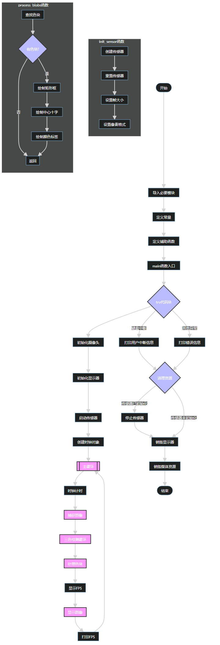
Code structure
Basic settings:
Set the display screen to 640×480 resolution
Define the detection thresholds for red, green and blue using the LAB color space
DRAW_COLORS and COLOR_LABELS arrays are used to draw markers and display color labels
Main improvements:
Detect three colors at the same time
Add color label text annotations to detected objects
Simplify the color processing logic
Workflow:
Initialize the camera and display
After entering the main loop:
Continuously capture images
Detect three colors in turn
Draw a rectangle, cross mark and color label for each detected object
Display frame rate information
Exception handling:
Keep the complete exception handling mechanism
Ensure that hardware resources are released correctly when the program ends
The detailed flow chart is as follows:
6. stm32 key code analysis
control.c
xxxxxxxxxxuint8_t get_point2_p() //Coordinate processing function{uint8_t lable, load_1, load_2 ,load_3 ,ret=0;if(DataDecode1(&Uart3_RingBuff,&lable, &load_1, &load_2,&load_3) == 0){if(lable == 0x00){rec_step_p[0][0] = load_1 + load_2 + load_3 ;// ret=1;
} else if(lable == 0xff){
rec_step_p[0][1] = load_1 + load_2 + load_3 ;// ret=1;
}
return ret;}}
This code adds the 3 frames of data transmitted by k230 together. As mentioned earlier, the coordinate data of k230 is split into 3 frames and then sent separately. Here, the data is added together to form the correct coordinates and assign the coordinates to the two-dimensional array.
xxxxxxxxxxget_point2_p();
set_target(rec_step_p[0][0],rec_step_p[0][1]);
This code uses the coordinates as the pid target value based on the face coordinates obtained above, and then controls the movement of the servo.
bsp_servo.c
xxxxxxxxxxServTypdef Xserv = {.pwm = 2000,.MAXPWM = 2500,.MINPWM = 500,.MIDPWM = 1400};
ServTypdef Yserv = {.pwm = 1000,.MAXPWM = 2300,.MINPWM = 500,.MIDPWM = 1000};
This code sets the starting position of the servo, so it needs to be modified to fit the vertex of the gimbal movement. I set the initial position of the gimbal at the upper right corner, and then the gimbal can be adjusted proportionally through the coordinate changes of the k230. If you need to adjust the gimbal position and fine-tune the position, you need to adjust this position parameter.
xxxxxxxxxxvoid servo_ctr(ServTypdef *servo, int PidInput){uint16_t CompSet = servo->MIDPWM + PidInput;
if( CompSet > servo->MAXPWM ){CompSet = servo->MAXPWM;} else if ( CompSet < servo->MINPWM ){CompSet = servo->MINPWM;}if(servo->pwm == CompSet){/*Avoid repeated changes in comparison value*/
return;}
if( servo == &Xserv ){
GPIO_SetBits(Servo_J1_PORT, Servo_J1_PIN ); //Set the servo level highdelay_us(CompSet); //Delay pulse value in microseconds
GPIO_ResetBits(Servo_J1_PORT, Servo_J1_PIN ); //Set the servo level lowdelay_ms(20 - CompSet/1000);}else if( servo == &Yserv ){
GPIO_SetBits(Servo_J2_PORT, Servo_J2_PIN ); //Set the servo level highdelay_us(CompSet); //Delay pulse value in microseconds
GPIO_ResetBits(Servo_J2_PORT, Servo_J2_PIN ); //Set the servo level lowdelay_ms(20 - CompSet/1000);}}
This code outputs the pid to the pwm, connects the pid to the pwm, and limits the pwm. It is also the core code for the servo movement. It controls the rotation of the servo through the delay and the change of the pwm, and connects the servo movement with the pwm.
pid.c
xxxxxxxxxxfloat pid_calculate(PID_TypeDef *PID, float CurrentValue){ PID->Err = PID->Target - CurrentValue; PID->Integral += PID->Err; if(PID->Integral > 7000){ PID->Integral = 7000; } if(PID->Integral < -7000){ PID->Integral = -7000; } //Points limit PID->PID_out = PID->Kp * PID->Err /*proportion*/ + PID->Ki * PID->Integral /*Points*/ + PID->Kd * (PID->Err - PID->LastErr); /*Derivative*/
PID->LastErr = PID->Err; return PID->PID_out;}
This code is the configuration of the position PID operation, including integral limiting. The position PID is calculated by the current deviation value (difference between target value and actual value), integral value (sum of past errors) and differential value (error change rate), and then the weighted addition of these three parts is used to obtain the PID output. If you want to fine-tune the code to achieve better results, you can fine-tune the PID parameters of the main function.
bsp_usart.c
xxxxxxxxxxuint8_t DataDecode1(RingBuff_t *ringbuff, uint8_t *data1, uint8_t *data2, uint8_t *data3,uint8_t *data4){ static uint8_t uart_dec_count; static uint8_t uart_rec_data[6]; uint8_t ret = 1;
if(Read_RingBuff(ringbuff, &uart_rec_data[uart_dec_count]) == RINGBUFF_ERR){ return 1;
} if((uart_dec_count == 0)&&(uart_rec_data[uart_dec_count] != 0x55)) { //Frame header 0x55 uart_rec_data[uart_dec_count] = 0; } else if((uart_dec_count == 1)&&(uart_rec_data[uart_dec_count] != 0xaa)){ //Second frame 0xaa uart_rec_data[uart_dec_count] = 0; uart_rec_data[uart_dec_count-1] = 0; uart_dec_count = 0; }else if((uart_dec_count == 6)&&(uart_rec_data[uart_dec_count] != 0xfa)){ //Frame end 0xfa uart_rec_data[uart_dec_count] = 0; uart_rec_data[uart_dec_count-1] = 0; uart_rec_data[uart_dec_count-2] = 0; uart_rec_data[uart_dec_count-3] = 0; uart_rec_data[uart_dec_count-4] = 0; uart_rec_data[uart_dec_count-5] = 0; uart_dec_count = 0; } else{ if(uart_dec_count == 6)//Successfully received one frame of data { *data1 = uart_rec_data[2]; *data2 = uart_rec_data[3]; *data3 = uart_rec_data[4]; *data4 = uart_rec_data[5]; ret = 0;
} uart_dec_count++; if(uart_dec_count == 7) { uart_dec_count = 0; }
} return ret;
}
This code is for receiving k230 data. It receives data only when the frame header is 0x55, the second data is 0xaa, and the frame tail is 0xfa. It locates a frame of data through three data. Since the coordinates of the four vertices transmitted from k230 are transmitted by splitting each vertex into three groups of data, the transmitted data is very large. In order to ensure that the transmitted data is accurate, three data are used to confirm a frame of data.
7. Effect description
The code sets the thresholds of three colors, and selects which color to recognize by modifying 0.1.2. When the selected color is recognized, k230 transmits the coordinates to the 2D gimbal, and then the 2D gimbal moves with the color to achieve the tracking effect.