Welcome to 2DOF PTZ repository
5. Gesture control
Gesture recognition
1. Introduction
Please read the information in the 24-way servo driver board and the STM32 introductory tutorial first to understand how to burn the program and the basics of getting started with STM32. This will make it easier to learn and burn the following programs.
2. Equipment list
3. Placement

The placement is as shown in the figure. You can choose our aluminum base frame as the base plate to fix the k230 and the gimbal, or you can choose a fixed base plate. The chassis can be glued to prevent the gimbal from moving too much and causing deviation. The k230 is fixed on the two-dimensional gimbal. When using the battery, if the gimbal rotates too much, you can moderately reduce the pid parameter.
4. Experimental preparation
First, build the 2D gimbal according to the 2D gimbal installation tutorial
Hardware wiring:

| 2D gimbal | 24-way servo driver board |
|---|---|
| X-axis servo | S1 |
| Y-axis servo | S2 |
| K230 vision module | 24-way motor driver board |
|---|---|
| 5V | 5V |
| GND | GND |
| TX | RX3 |
| RX | TX3 |
Note: When plugging in the servo cable, be sure to align the yellow cable with the yellow GPIO port of the 24-way servo driver board, and the brown cable with the black GPIO port of the 24-way servo driver board.
5. K230 key code analysis
x
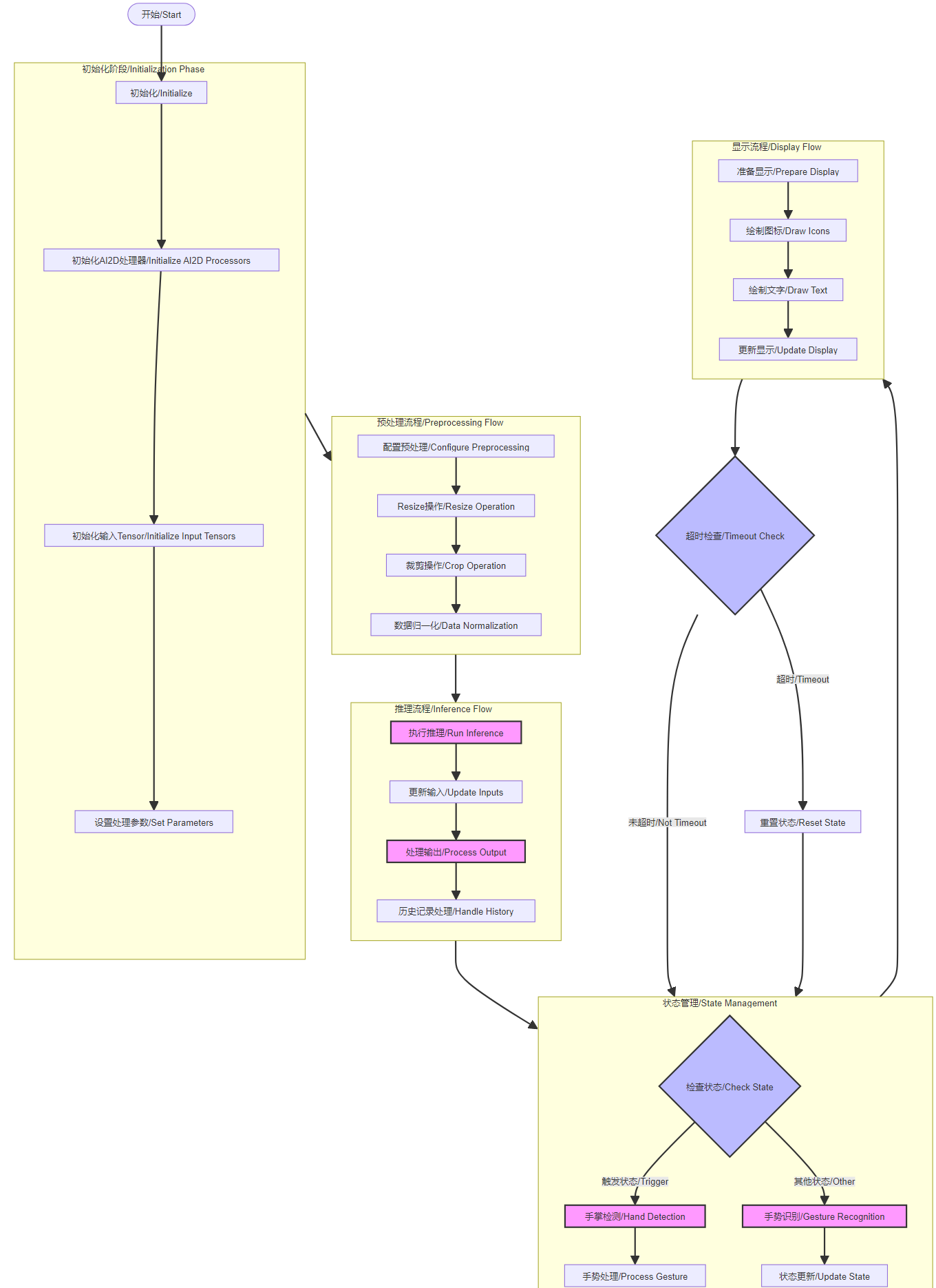
def run(self, input_np):• """ 运行手势识别 / Run gesture recognition• 参数 / Parameter: input_np: 输入图像 / Input image• 返回 / Returns: 根据当前状态返回检测结果或识别结果 / Returns detection or recognition results based on current state """ if self.cur_state == self.TRIGGER: # 手掌检测模式 / Hand detection mode det_boxes = self.hand_det.run(input_np) boxes = [] gesture_res = []• for det_box in det_boxes: # 获取检测框坐标 / Get detection box coordinates x1, y1, x2, y2 = det_box[2], det_box[3], det_box[4], det_box[5] w, h = int(x2 - x1), int(y2 - y1)• # 过滤无效检测框 / Filter invalid detection boxes if (h < (0.1 * self.rgb888p_size[1])): continue if (w < (0.25 * self.rgb888p_size[0]) and ((x1 < (0.03 * self.rgb888p_size[0])) or (x2 > (0.97 * self.rgb888p_size[0])))): continue if (w < (0.15 * self.rgb888p_size[0]) and ((x1 < (0.01 * self.rgb888p_size[0])) or (x2 > (0.99 * self.rgb888p_size[0])))): continue• # 执行关键点检测 / Perform keypoint detection self.hand_kp.config_preprocess(det_box) hk_results, gesture_str = self.hand_kp.run(input_np) boxes.append(det_box) gesture_res.append((hk_results, gesture_str))• return boxes, gesture_res else: # 动态手势识别模式 / Dynamic gesture recognition mode idx, avg_logit = self.dg.run(input_np, self.his_logit, self.history) return idx, avg_logit• def draw_result(self, pl, output1, output2): """ 绘制识别结果 / Draw recognition results• 参数 / Parameters: pl: 绘图层对象 / Drawing layer object output1: 第一阶段输出(检测框) / First stage output (detection boxes) output2: 第二阶段输出(关键点和手势) / Second stage output (keypoints and gestures) """ # 清空绘图缓存 / Clear drawing cache pl.osd_img.clear() draw_img_np = np.zeros((self.display_size[1], self.display_size[0], 4), dtype=np.uint8) draw_img = image.Image(self.display_size[0], self.display_size[1], image.ARGB8888, alloc=image.ALLOC_REF, data=draw_img_np)• if self.cur_state == self.TRIGGER: # 触发状态下的处理 / Processing in trigger state for i in range(len(output1)): hk_results, gesture = output2[i][0], output2[i][1]• # 检测到"five"或"yeah"手势 / Detect "five" or "yeah" gesture if ((gesture == "five") or (gesture == "yeah")): # 计算手势方向向量 / Calculate gesture direction vector v_x = hk_results[24] - hk_results[0] v_y = hk_results[25] - hk_results[1] angle = self.hand_kp.hk_vector_2d_angle([v_x,v_y], [1.0,0.0]) if (v_y > 0): angle = 360 - angle• # 根据角度判断手势方向 / Determine gesture direction based on angle if ((70.0 <= angle) and (angle < 110.0)): # 向上 / Upward if ((self.pre_state != self.UP) or (self.pre_state != self.MIDDLE)): self.vec_flag.append(self.pre_state) if ((len(self.vec_flag) > 10) or (self.pre_state == self.UP) or (self.pre_state == self.MIDDLE) or (self.pre_state == self.TRIGGER)): draw_img_np[:self.bin_height,:self.bin_width,:] = self.shang_argb self.cur_state = self.UP• elif ((110.0 <= angle) and (angle < 225.0)): # 向右 / Rightward if (self.pre_state != self.RIGHT): self.vec_flag.append(self.pre_state) if ((len(self.vec_flag) > 10) or (self.pre_state == self.RIGHT) or (self.pre_state == self.TRIGGER)): draw_img_np[:self.bin_width,:self.bin_height,:] = self.you_argb self.cur_state = self.RIGHT• elif((225.0 <= angle) and (angle < 315.0)): # 向下 / Downward if (self.pre_state != self.DOWN): self.vec_flag.append(self.pre_state) if ((len(self.vec_flag) > 10) or (self.pre_state == self.DOWN) or (self.pre_state == self.TRIGGER)): draw_img_np[:self.bin_height,:self.bin_width,:] = self.xia_argb self.cur_state = self.DOWN• else: # 向左 / Leftward if (self.pre_state != self.LEFT): self.vec_flag.append(self.pre_state) if ((len(self.vec_flag) > 10) or (self.pre_state == self.LEFT) or (self.pre_state == self.TRIGGER)): draw_img_np[:self.bin_width,:self.bin_height,:] = self.zuo_argb self.cur_state = self.LEFT• self.m_start = time.time_ns() self.his_logit = []• else: # 非触发状态下的处理 / Processing in non-trigger state idx, avg_logit = output1, output2[0]• # 处理不同状态下的手势动作 / Handle gesture actions in different states if (self.cur_state == self.UP): draw_img_np[:self.bin_height,:self.bin_width,:] = self.shang_argb if ((idx == 15) or (idx == 10)): # 向上挥动确认 / Upward wave confirmation self.vec_flag.clear() if (((avg_logit[idx] >= 0.7) and (len(self.his_logit) >= 2)) or ((avg_logit[idx] >= 0.3) and (len(self.his_logit) >= 4))): self.s_start = time.time_ns() self.cur_state = self.TRIGGER self.draw_state = self.DOWN self.history = [2] self.pre_state = self.UP elif ((idx == 25) or (idx == 26)): # 中间位置确认 / Middle position confirmation self.vec_flag.clear() if (((avg_logit[idx] >= 0.4) and (len(self.his_logit) >= 2)) or ((avg_logit[idx] >= 0.3) and (len(self.his_logit) >= 3))): self.s_start = time.time_ns() self.cur_state = self.TRIGGER self.draw_state = self.MIDDLE self.history = [2] self.pre_state = self.MIDDLE else: self.his_logit.clear()• # 处理其他方向的状态(RIGHT/DOWN/LEFT)的逻辑类似 # Similar logic for other directional states (RIGHT/DOWN/LEFT) elif (self.cur_state == self.RIGHT): draw_img_np[:self.bin_width,:self.bin_height,:] = self.you_argb if ((idx==16)or(idx==11)) : self.vec_flag.clear() if (((avg_logit[idx] >= 0.4) and (len(self.his_logit) >= 2)) or ((avg_logit[idx] >= 0.3) and (len(self.his_logit) >= 3))): self.s_start = time.time_ns() self.cur_state = self.TRIGGER self.draw_state = self.RIGHT self.history = [2] self.pre_state = self.RIGHT else: self.his_logit.clear() elif (self.cur_state == self.DOWN): draw_img_np[:self.bin_height,:self.bin_width,:] = self.xia_argb if ((idx==18)or(idx==13)): self.vec_flag.clear() if (((avg_logit[idx] >= 0.4) and (len(self.his_logit) >= 2)) or ((avg_logit[idx] >= 0.3) and (len(self.his_logit) >= 3))): self.s_start = time.time_ns() self.cur_state = self.TRIGGER self.draw_state = self.UP self.history = [2] self.pre_state = self.DOWN else: self.his_logit.clear() elif (self.cur_state == self.LEFT): draw_img_np[:self.bin_width,:self.bin_height,:] = self.zuo_argb if ((idx==17)or(idx==12)): self.vec_flag.clear() if (((avg_logit[idx] >= 0.4) and (len(self.his_logit) >= 2)) or ((avg_logit[idx] >= 0.3) and (len(self.his_logit) >= 3))): self.s_start = time.time_ns() self.cur_state = self.TRIGGER self.draw_state = self.LEFT self.history = [2] self.pre_state = self.LEFT else: self.his_logit.clear()• self.elapsed_time = round((time.time_ns() - self.m_start)/1000000)• # 超时处理 / Timeout handling if ((self.cur_state != self.TRIGGER) and (self.elapsed_time > 2000)): self.cur_state = self.TRIGGER self.pre_state = self.TRIGGER• # 绘制结果显示 / Draw result display self.elapsed_ms_show = round((time.time_ns()-self.s_start)/1000000) if (self.elapsed_ms_show < 1000): gesture_dir = "" # 根据不同状态绘制不同的箭头和文字 / Draw different arrows and text based on state if (self.draw_state == self.UP): draw_img.draw_arrow(self.display_size[0]//2, self.display_size[1]//2, self.display_size[0]//2, self.display_size[1]//2-100, (155,170,190,230), thickness=13) draw_img.draw_string_advanced(self.display_size[0]//2-50, self.display_size[1]//2-50, 32, "向上 UP") gesture_dir = "UP" elif (self.draw_state == self.LEFT): draw_img.draw_arrow(self.display_size[0]//2, self.display_size[1]//2, self.display_size[0]//2-100, self.display_size[1]//2, (155,170,190,230), thickness=13) draw_img.draw_string_advanced(self.display_size[0]//2-50, self.display_size[1]//2-50, 32, "向左 LEFT") gesture_dir = "LEFT" elif (self.draw_state == self.DOWN): draw_img.draw_arrow(self.display_size[0]//2,self.display_size[1]//2,self.display_size[0]//2,self.display_size[1]//2+100, (155,170,190,230), thickness=13) # 判断为向下挥动时,画一个向下的箭头 draw_img.draw_string_advanced(self.display_size[0]//2-50,self.display_size[1]//2-50,32,"向下 DOWN") gesture_dir = "DOWN" elif (self.draw_state == self.RIGHT): draw_img.draw_arrow(self.display_size[0]//2,self.display_size[1]//2,self.display_size[0]//2+100,self.display_size[1]//2, (155,170,190,230), thickness=13) # 判断为向左挥动时,画一个向左的箭头 draw_img.draw_string_advanced(self.display_size[0]//2-50,self.display_size[1]//2-50,32,"向右 RIGHT") gesture_dir = "RIGHT" elif (self.draw_state == self.MIDDLE): draw_img.draw_circle(self.display_size[0]//2,self.display_size[1]//2,100, (255,170,190,230), thickness=2, fill=True) # 判断为五指捏合手势时,画一个实心圆 draw_img.draw_string_advanced(self.display_size[0]//2-50,self.display_size[1]//2-50,32,"中间 MIDDLE") gesture_dir = "MIDDLE" if len(gesture_dir) > 0 and self.tx_flag == False: self.tx_flag = True else: self.draw_state = self.TRIGGER• # 更新显示 / Update display pl.osd_img.copy_from(draw_img)
Flowchart
6. stm32 key code analysis
control.c
xxxxxxxxxxuint8_t get_point2_p() //Coordinate processing function{uint8_t lable, load_1, load_2 ,load_3 ,ret=0;if(DataDecode1(&Uart3_RingBuff,&lable, &load_1, &load_2,&load_3) == 0){if(lable == 0x00){rec_step_p[0][0] = load_1 + load_2 + load_3 ;// ret=1;
} else if(lable == 0xff){
rec_step_p[0][1] = load_1 + load_2 + load_3 ;// ret=1;
}
return ret;}}
This code adds together the three frames of data transmitted by k230. As mentioned earlier, the coordinate data of k230 is split into three frames and then sent separately. Here, the data is added together to form the correct coordinates and the coordinates are assigned to the two-dimensional array.
xxxxxxxxxxvoid mode_1pro(){
TIM_ITConfig(TIM1,TIM_IT_Update, ENABLE); TIM_Cmd(TIM4, ENABLE); USART_Cmd(USART3, ENABLE); get_hand();


if(mode_flag == 0 && rec_hand[0][1] ==1){ USART_Cmd(USART3, DISABLE); go_to_point(0, 0, 400, 0);
go_to_point(400, 0, 0, 0); TIM_ITConfig(TIM1,TIM_IT_Update, DISABLE); TIM_Cmd(TIM4, DISABLE); rec_hand[0][1] =0;


}
if(mode_flag == 0 && rec_hand[0][3] ==1){ USART_Cmd(USART3, DISABLE); go_to(0, 0, 400, 0); go_to(400, 0, 0, 0); TIM_ITConfig(TIM1,TIM_IT_Update, DISABLE); TIM_Cmd(TIM4, DISABLE); rec_hand[0][3] =0;

} if(mode_flag == 0 && rec_hand[0][2] ==1){ USART_Cmd(USART3, DISABLE); go_to_point(0, 0, 0, 400);
go_to_point(0, 400, 0, 0);
TIM_ITConfig(TIM1,TIM_IT_Update, DISABLE); TIM_Cmd(TIM4, DISABLE); rec_hand[0][2] =0;


} if(mode_flag == 0 && rec_hand[0][0] ==1){USART_Cmd(USART3, DISABLE);go_to(0, 0, 0, 300);go_to(0, 300, 0, 0);TIM_ITConfig(TIM1,TIM_IT_Update, DISABLE);TIM_Cmd(TIM4, DISABLE);rec_hand[0][0] =0;
}}
This code is to perform movement according to the gesture information obtained above.
xxxxxxxxxxvoid go_to_point(uint16_t now_x, uint16_t now_y, uint16_t targ_x, uint16_t targ_y){ uint16_t i; float step_num = 200;/* 200 steps*/ float step_x, step_y; /* step value */ float going_x = now_x, going_y = now_y; /* Current target value*/
step_x = (targ_x - now_x) / step_num; step_y = (targ_y - now_y) / step_num;
for(i = 0; i < step_num; i++){
kfp_x.source = step_x; kfp_y.source = step_y; kfp_x.out = KalmanFilter(&kfp_x, kfp_x.source);kfp_y.out = KalmanFilter(&kfp_y, kfp_y.source);going_x += kfp_x.out;going_y += kfp_y.out;
set_target(going_x, going_y);}}
This code subdivides the coordinates of the two points obtained, thereby dividing the two points of the rectangle into many points, and then performing pid calculations between many points to make the servo movement more accurate.
xxxxxxxxxxvoid go_to(uint16_t now_x, uint16_t now_y, uint16_t targ_x, uint16_t targ_y){ uint16_t i; float step_num = 100; float step_x, step_y; float going_x = now_x, going_y = now_y;
step_x = (targ_x - now_x) / step_num; step_y = (targ_y - now_y) / step_num;
for(i = 0; i < step_num;i++){

kfp_x.source = step_x; kfp_y.source = step_y; kfp_x.out = KalmanFilter(&kfp_x, kfp_x.source); kfp_y.out = KalmanFilter(&kfp_y, kfp_y.source);
going_x += kfp_x.out;going_y += kfp_y.out;
set_target(-going_x, -going_y);
}}
This code subdivides the coordinates of the two points obtained, thereby dividing the two points of the rectangle into many points, and then performing pid calculations between many points to make the servo movement more accurate.
bsp_servo.c
xxxxxxxxxxServTypdef Xserv = {.pwm = 1600,.MAXPWM = 2400,.MINPWM = 500,.MIDPWM = 1400};
ServTypdef Yserv = {.pwm = 1600,.MAXPWM = 2500,.MINPWM = 300,.MIDPWM = 1400};
This code sets the starting position of the servo, so it needs to be modified to fit the vertex of the gimbal movement. I set the initial position of the gimbal at the middle point, and change the starting position of the servo through this.
xxxxxxxxxxvoid servo_ctr(ServTypdef *servo, int PidInput){uint16_t CompSet = servo->MIDPWM + PidInput;
if( CompSet > servo->MAXPWM ){CompSet = servo->MAXPWM;} else if ( CompSet < servo->MINPWM ){CompSet = servo->MINPWM;}if(servo->pwm == CompSet){/*Avoid repeated changes in comparison value*/
return;}
if( servo == &Xserv ){
GPIO_SetBits(Servo_J1_PORT, Servo_J1_PIN ); //Set the servo level highdelay_us(CompSet); //Delay pulse value in microseconds
GPIO_ResetBits(Servo_J1_PORT, Servo_J1_PIN ); //Set the servo level lowdelay_ms(20 - CompSet/1000);}else if( servo == &Yserv ){
GPIO_SetBits(Servo_J2_PORT, Servo_J2_PIN ); //Set the servo level highdelay_us(CompSet); //Delay pulse value in microseconds
GPIO_ResetBits(Servo_J2_PORT, Servo_J2_PIN ); //Set the servo level lowdelay_ms(20 - CompSet/1000);}}
This code outputs the pid to the pwm, connects the pid to the pwm, and limits the pwm. It is also the core code for the servo movement. It controls the rotation of the servo through the delay and the change of the pwm, and connects the servo movement with the pwm.
pid.c
xxxxxxxxxxfloat pid_calculate(PID_TypeDef *PID, float CurrentValue){ PID->Err = PID->Target - CurrentValue; PID->Integral += PID->Err; if(PID->Integral > 7000){ PID->Integral = 7000; } if(PID->Integral < -7000){ PID->Integral = -7000; } //Points limit PID->PID_out = PID->Kp * PID->Err /*proportion*/ + PID->Ki * PID->Integral /*Points*/ + PID->Kd * (PID->Err - PID->LastErr); /*Derivative*/
PID->LastErr = PID->Err; return PID->PID_out;}
This code is the configuration of the position PID operation, including integral limiting. The position PID is calculated by the current deviation value (difference between target value and actual value), integral value (sum of past errors) and differential value (error change rate), and then the weighted addition of these three parts is used to obtain the PID output. If you want to fine-tune the code to achieve better results, you can fine-tune the PID parameters of the main function.
bsp_usart.c
xxxxxxxxxxuint8_t DataDecode1(RingBuff_t *ringbuff, uint8_t *data1, uint8_t *data2, uint8_t *data3,uint8_t *data4){ static uint8_t uart_dec_count; static uint8_t uart_rec_data[6]; uint8_t ret = 1;
if(Read_RingBuff(ringbuff, &uart_rec_data[uart_dec_count]) == RINGBUFF_ERR){ return 1;
} if((uart_dec_count == 0)&&(uart_rec_data[uart_dec_count] != 0x55)) { //Frame header 0x55 uart_rec_data[uart_dec_count] = 0; } else if((uart_dec_count == 1)&&(uart_rec_data[uart_dec_count] != 0xaa)){ //Second frame 0xaa uart_rec_data[uart_dec_count] = 0; uart_rec_data[uart_dec_count-1] = 0; uart_dec_count = 0; }else if((uart_dec_count == 6)&&(uart_rec_data[uart_dec_count] != 0xfa)){ //Frame end 0xfa uart_rec_data[uart_dec_count] = 0; uart_rec_data[uart_dec_count-1] = 0; uart_rec_data[uart_dec_count-2] = 0; uart_rec_data[uart_dec_count-3] = 0; uart_rec_data[uart_dec_count-4] = 0; uart_rec_data[uart_dec_count-5] = 0; uart_dec_count = 0; } else{ if(uart_dec_count == 6)//Successfully received one frame of data { *data1 = uart_rec_data[2]; *data2 = uart_rec_data[3]; *data3 = uart_rec_data[4]; *data4 = uart_rec_data[5]; ret = 0;
} uart_dec_count++; if(uart_dec_count == 7) { uart_dec_count = 0; }
} return ret;
}
This code is for receiving k230 data. It receives data only when the frame header is 0x55, the second data is 0xaa, and the frame tail is 0xfa. It locates a frame of data through three data. Since the coordinates of the four vertices transmitted from k230 are transmitted by splitting each vertex into three groups of data, the transmitted data is very large. In order to ensure that the transmitted data is accurate, three data are used to confirm a frame of data.
7. Effect display
When k230 recognizes a gesture, the transmission information controls the movement of k230. If the gesture is upward, the gimbal moves upward; if the gesture is downward, the gimbal moves downward; if the gesture is left, the gimbal moves left and right; if the gesture is right, the gimbal moves right.