Welcome to 2DOF PTZ repository
6. Human tracking alarm
Human body recognition alarm tracking
1. Introduction
Please read the information in the 24-way servo driver board and the STM32 introductory tutorial first to understand how to burn the program and the basics of STM32. This will make it easier to learn and burn the following programs.
2. Equipment list
3. Placement
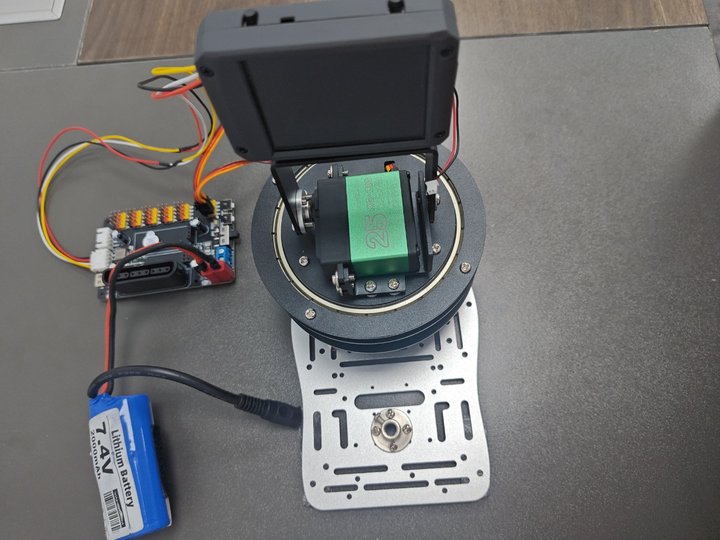
The placement is as shown in the figure. You can choose our aluminum base frame as the base plate to fix the k230 and the gimbal, or you can choose a fixed base plate. The chassis can be glued to prevent the gimbal from moving too much and causing deviation. The k230 is fixed on the two-dimensional gimbal. When using the battery, if the gimbal rotates too much, you can moderately reduce the pid parameter.
4. Experimental preparation
First, build the 2D gimbal according to the 2D gimbal installation tutorial
Hardware wiring:

| 2D gimbal | 24-way servo driver board |
|---|---|
| X-axis servo | S1 |
| Y-axis servo | S2 |
| K230 vision module | 24-way motor driver board |
|---|---|
| 5V | 5V |
| GND | GND |
| TX | RX3 |
| RX | TX3 |
Note: When plugging in the servo cable, be sure to align the yellow cable with the yellow GPIO port of the 24-way servo driver board, and the brown cable with the black GPIO port of the 24-way servo driver board.
5. K230 key code analysis
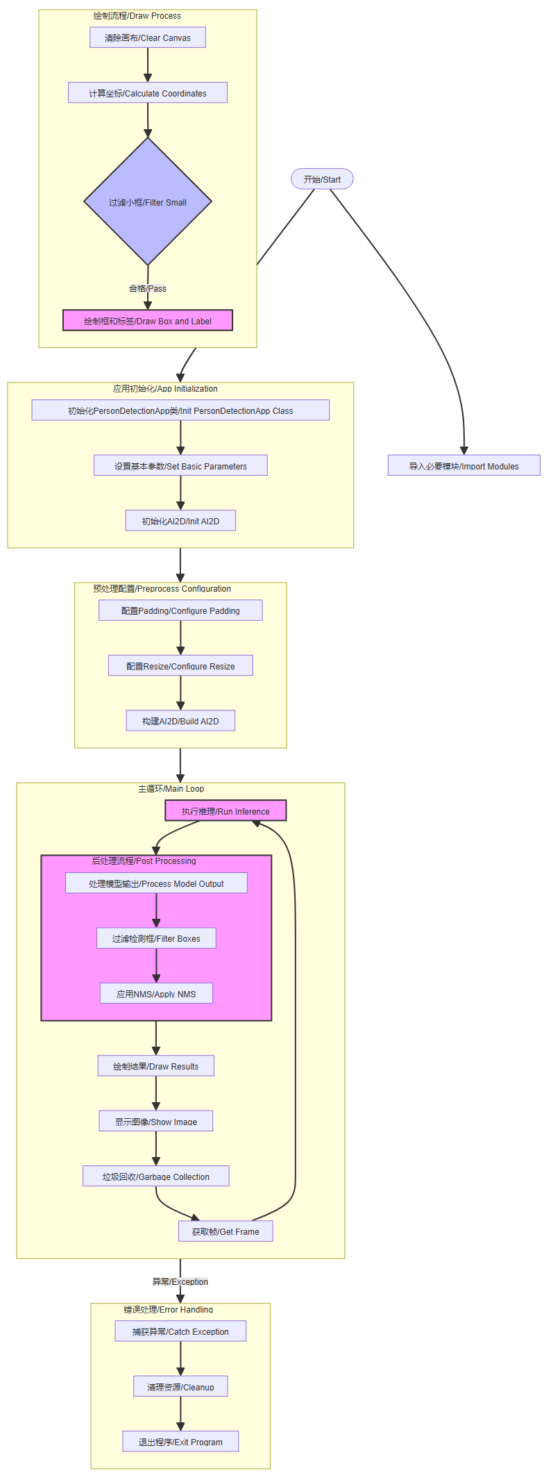
Code structure
Main program flow:
Initialize PipeLine
Create PipeLine instance
Execute Demo function
Demo execution flow:
Initialize parameters (model path, threshold, etc.)
Initialize human body detection class
Enter the main loop to process images
Human body detection class function:
Class initialization (setting parameters and AI2D)
Preprocessing process (padding and resize)
Postprocessing process (processing detection results)
Result drawing (drawing detection box and label)
Data transmission (giving coordinate data to stm32)
Exception handling:
Capture exceptions and print information
Execute deinitialization cleanup
Code Snippet
xfrom libs.PipeLine import PipeLine, ScopedTimingfrom libs.AIBase import AIBasefrom libs.AI2D import Ai2dfrom ybUtils.YbBuzzer import YbBuzzerfrom libs.YbProtocol import YbProtocolfrom ybUtils.YbUart import YbUartimport osimport ujsonfrom media.media import *from time import *import nncase_runtime as nnimport ulab.numpy as npimport timeimport utimeimport imageimport randomimport gcimport sysimport aicube
person_det = None
buzzer = YbBuzzer()
last_cx = 0last_cy = 0# uart = Noneuart = YbUart(baudrate=115200)pto = YbProtocol()
def conversion_postion(x,y): if x > 510: x_h = 255 x_l = 255 x_z = x-255-255 elif 510>=x>=255: x_h = 255 x_l = x-255 x_z = 0 else: x_h = x x_l = 0 x_z = 0 if y > 510: y_h = 255 y_l = 255 y_z = y-255-255 elif 510>=y>=255: y_h = 255 y_l = y-255 y_z = 0 else: y_h = y y_l = 0 y_z = 0 return x_h,x_l,x_z,y_h,y_l,y_z# 自定义人体检测类# (Custom person detection class)class PersonDetectionApp(AIBase): def __init__(self, kmodel_path, model_input_size, labels, anchors, confidence_threshold=0.2, nms_threshold=0.5, nms_option=False, strides=[8, 16, 32], rgb888p_size=[224, 224], display_size=[640, 360], debug_mode=0): """ 初始化人体检测应用类 (Initialize the person detection application class)
参数: kmodel_path: 模型文件路径 (kmodel_path: Path to the model file) model_input_size: 模型输入分辨率 (model_input_size: Model input resolution) labels: 标签列表 (labels: List of labels) anchors: 检测anchors设置 (anchors: Detection anchor settings) confidence_threshold: 置信度阈值 (confidence_threshold: Confidence threshold) nms_threshold: nms阈值 (nms_threshold: NMS threshold) nms_option: nms是否开启 (nms_option: Whether NMS is enabled) strides: 特征图降采样倍数 (strides: Feature map downsampling factor) rgb888p_size: 传感器输入图像分辨率 (rgb888p_size: Sensor input image resolution) display_size: 显示分辨率 (display_size: Display resolution) debug_mode: 调试模式级别 (debug_mode: Debug mode level) """ super().__init__(kmodel_path, model_input_size, rgb888p_size, debug_mode) self.kmodel_path = kmodel_path # 模型输入分辨率 # (Model input resolution) self.model_input_size = model_input_size # 标签 # (Labels) self.labels = labels # 检测anchors设置 # (Detection anchor settings) self.anchors = anchors # 特征图降采样倍数 # (Feature map downsampling factor) self.strides = strides # 置信度阈值设置 # (Confidence threshold setting) self.confidence_threshold = confidence_threshold # nms阈值设置 # (NMS threshold setting) self.nms_threshold = nms_threshold self.nms_option = nms_option # sensor给到AI的图像分辨率 # (Image resolution from sensor to AI) self.rgb888p_size = [ALIGN_UP(rgb888p_size[0], 16), rgb888p_size[1]] # 显示分辨率 # (Display resolution) self.display_size = [ALIGN_UP(display_size[0], 16), display_size[1]] self.debug_mode = debug_mode # Ai2d实例,用于实现模型预处理 # (Ai2d instance for model preprocessing) self.ai2d = Ai2d(debug_mode) # 设置Ai2d的输入输出格式和类型 # (Set Ai2d input and output formats and types) self.ai2d.set_ai2d_dtype(nn.ai2d_format.NCHW_FMT, nn.ai2d_format.NCHW_FMT, np.uint8, np.uint8)
# 配置预处理操作,这里使用了pad和resize,Ai2d支持crop/shift/pad/resize/affine,具体代码请打开/sdcard/app/libs/AI2D.py查看 # (Configure preprocessing operations, using pad and resize here, Ai2d supports crop/shift/pad/resize/affine) def config_preprocess(self, input_image_size=None): """ 配置模型输入数据的预处理操作 (Configure preprocessing operations for model input data)
参数: input_image_size: 输入图像尺寸,如果为None则使用默认rgb888p_size (input_image_size: Input image size, if None uses default rgb888p_size) """ with ScopedTiming("set preprocess config", self.debug_mode > 0): # 初始化ai2d预处理配置,默认为sensor给到AI的尺寸,您可以通过设置input_image_size自行修改输入尺寸 # (Initialize ai2d preprocessing configuration, default is the size from sensor to AI) ai2d_input_size = input_image_size if input_image_size else self.rgb888p_size top, bottom, left, right = self.get_padding_param() self.ai2d.pad([0, 0, 0, 0, top, bottom, left, right], 0, [0, 0, 0]) self.ai2d.resize(nn.interp_method.tf_bilinear, nn.interp_mode.half_pixel) self.ai2d.build([1, 3, ai2d_input_size[1], ai2d_input_size[0]], [1, 3, self.model_input_size[1], self.model_input_size[0]])
# 自定义当前任务的后处理 # (Custom post-processing for the current task) def postprocess(self, results): """ 对模型输出进行后处理 (Post-process the model output)
参数: results: 模型的原始输出 (results: Raw output from the model)
返回: 处理后的检测结果 (Processed detection results) """ with ScopedTiming("postprocess", self.debug_mode > 0): # 这里使用了aicube模型的后处理接口anchorbasedet_post_preocess # (Use the anchorbasedet_post_process interface from the aicube model for post-processing) dets = aicube.anchorbasedet_post_process(results[0], results[1], results[2], self.model_input_size, self.rgb888p_size, self.strides, len(self.labels), self.confidence_threshold, self.nms_threshold, self.anchors, self.nms_option) return dets
# 绘制结果 # (Draw results) def draw_result(self, pl, dets):
""" 在画布上绘制人体检测结果 (Draw person detection results on the canvas)
参数: pl: 画布对象 (pl: Canvas object) dets: 检测结果 (dets: Detection results) """ with ScopedTiming("display_draw", self.debug_mode > 0): if dets: pl.osd_img.clear() for det_box in dets: # 计算检测框在显示分辨率下的坐标和尺寸 # (Calculate the coordinates and size of the detection box in the display resolution) x1, y1, x2, y2 = det_box[2], det_box[3], det_box[4], det_box[5] w = float(x2 - x1) * self.display_size[0] // self.rgb888p_size[0] h = float(y2 - y1) * self.display_size[1] // self.rgb888p_size[1] x1 = int(x1 * self.display_size[0] // self.rgb888p_size[0]) y1 = int(y1 * self.display_size[1] // self.rgb888p_size[1]) x2 = int(x2 * self.display_size[0] // self.rgb888p_size[0]) y2 = int(y2 * self.display_size[1] // self.rgb888p_size[1])
# 过滤掉尺寸太小的检测框 # (Filter out detection boxes that are too small) if (h < (0.1 * self.display_size[0])): continue if (w < (0.25 * self.display_size[0]) and ((x1 < (0.03 * self.display_size[0])) or (x2 > (0.97 * self.display_size[0])))): continue if (w < (0.15 * self.display_size[0]) and ((x1 < (0.01 * self.display_size[0])) or (x2 > (0.99 * self.display_size[0])))): continue
# 在画布上绘制检测框和标签 # (Draw the detection box and label on the canvas) pl.osd_img.draw_rectangle(x1, y1, int(w), int(h), color=(255, 0, 255, 0), thickness=2)# uart.send(f"${x1},{y1},{w},{h}#") pl.osd_img.draw_string_advanced(x1, y1 - 50, 32, " " + self.labels[det_box[0]] + " " + str(round(det_box[1], 2)), color=(255, 0, 255, 0)) #pto_data = pto.get_person_detect_data(x1, y1, w, h) cx_h,cx_l,cx_z,cy_h,cy_l,cy_z=conversion_postion(x1,y1)
buzzer.beep() ] uart.write(bytearray([0x55,0xaa,0x00,int(cx_h),int(cx_l),int(cx_z),0xfa])) uart.write(bytearray([0x55,0xaa,0xff,int(cy_h),int(cy_l),int(cy_z),0xfa]))
else: pl.osd_img.clear()
# 计算padding参数 # (Calculate padding parameters) def get_padding_param(self): """ 计算将输入图像等比缩放到模型输入尺寸时需要的padding参数 (Calculate the padding parameters required to proportionally scale the input image to the model input size)
返回: padding参数 [top, bottom, left, right] (Padding parameters [top, bottom, left, right]) """ dst_w = self.model_input_size[0] dst_h = self.model_input_size[1] input_width = self.rgb888p_size[0] input_high = self.rgb888p_size[1] ratio_w = dst_w / input_width ratio_h = dst_h / input_high if ratio_w < ratio_h: ratio = ratio_w else: ratio = ratio_h new_w = (int)(ratio * input_width) new_h = (int)(ratio * input_high) dw = (dst_w - new_w) / 2 dh = (dst_h - new_h) / 2 top = int(round(dh - 0.1)) bottom = int(round(dh + 0.1)) left = int(round(dw - 0.1)) right = int(round(dw - 0.1)) return top, bottom, left, right
def exce_demo(pl): """ 执行人体检测演示 (Execute person detection demo)
参数: pl: PipeLine对象 (pl: PipeLine object) """ global person_det
display_mode = pl.display_mode rgb888p_size = pl.rgb888p_size display_size = pl.display_size
# 设置模型路径和其他参数 # (Set model path and other parameters) kmodel_path = "/sdcard/kmodel/person_detect_yolov5n.kmodel" # 其它参数设置 # (Other parameter settings) confidence_threshold = 0.7 nms_threshold = 0.7 labels = ["person"] anchors = [10, 13, 16, 30, 33, 23, 30, 61, 62, 45, 59, 119, 116, 90, 156, 198, 373, 326]
try: # 初始化自定义人体检测实例 # (Initialize the custom person detection instance) person_det = PersonDetectionApp(kmodel_path, model_input_size=[640, 640], labels=labels, anchors=anchors, confidence_threshold=confidence_threshold, nms_threshold=nms_threshold, nms_option=False, strides=[8, 16, 32], rgb888p_size=rgb888p_size, display_size=display_size, debug_mode=0) person_det.config_preprocess() while True: with ScopedTiming("total", 1): # 获取当前帧数据 # (Get the current frame data) #•buzzer = YbBuzzer() img = pl.get_frame() # 推理当前帧 # (Inference on the current frame) res = person_det.run(img) # 绘制结果到PipeLine的osd图像 # (Draw the results on the PipeLine's osd image) person_det.draw_result(pl, res)
# 显示当前的绘制结果 # (Display the current drawing results) pl.show_image() gc.collect() #except Exception as e: # print("人体检测功能退出") # (Person detection function exited) finally: person_det.deinit() # 反初始化 # (Deinitialize)
def exit_demo(): """ 退出人体检测演示 (Exit person detection demo) """ global person_det person_det.deinit()
if __name__ == "__main__":
rgb888p_size = [640, 360] display_size = [640, 480] display_mode = "lcd"
# 初始化PipeLine,用于图像处理流程 # (Initialize PipeLine for image processing) pl = PipeLine(rgb888p_size=rgb888p_size, display_size=display_size, display_mode=display_mode) pl.create() # 创建PipeLine实例 # (Create PipeLine instance) # 初始化自定义人脸检测实例 # (Initialize the custom person detection instance) exce_demo(pl)
Flowchart
6. stm32 key code analysis
control.c
xxxxxxxxxxuint8_t get_point2_p() //Coordinate processing function{uint8_t lable, load_1, load_2 ,load_3 ,ret=0;if(DataDecode1(&Uart3_RingBuff,&lable, &load_1, &load_2,&load_3) == 0){if(lable == 0x00){rec_step_p[0][0] = load_1 + load_2 + load_3 ;// ret=1;
} else if(lable == 0xff){
rec_step_p[0][1] = load_1 + load_2 + load_3 ;// ret=1;
}
return ret;}}
This code adds the 3 frames of data transmitted by k230 together. As mentioned earlier, the coordinate data of k230 is split into 3 frames and then sent separately. Here, the data is added together to form the correct coordinates and assign the coordinates to the two-dimensional array.
xxxxxxxxxxget_point2_p();
set_target(rec_step_p[0][0],rec_step_p[0][1]);
This code uses the coordinates as the pid target value based on the face coordinates obtained above, and then controls the movement of the servo.
bsp_servo.c
xxxxxxxxxxServTypdef Xserv = {.pwm = 2000,.MAXPWM = 2500,.MINPWM = 500,.MIDPWM = 1400};
ServTypdef Yserv = {.pwm = 1000,.MAXPWM = 2300,.MINPWM = 500,.MIDPWM = 1000};
This code sets the starting position of the servo, so it needs to be modified to fit the vertex of the gimbal movement. I set the initial position of the gimbal at the upper right corner, and then the gimbal can be adjusted proportionally through the coordinate changes of the k230. If you need to adjust the gimbal position and fine-tune the position, you need to adjust this position parameter.
xxxxxxxxxxvoid servo_ctr(ServTypdef *servo, int PidInput){uint16_t CompSet = servo->MIDPWM + PidInput;
if( CompSet > servo->MAXPWM ){CompSet = servo->MAXPWM;} else if ( CompSet < servo->MINPWM ){CompSet = servo->MINPWM;}if(servo->pwm == CompSet){/*Avoid repeated changes in comparison value*/
return;}
if( servo == &Xserv ){
GPIO_SetBits(Servo_J1_PORT, Servo_J1_PIN ); //Set the servo level highdelay_us(CompSet); //Delay pulse value in microseconds
GPIO_ResetBits(Servo_J1_PORT, Servo_J1_PIN ); //Set the servo level lowdelay_ms(20 - CompSet/1000);}else if( servo == &Yserv ){
GPIO_SetBits(Servo_J2_PORT, Servo_J2_PIN ); //Set the servo level highdelay_us(CompSet); //Delay pulse value in microseconds
GPIO_ResetBits(Servo_J2_PORT, Servo_J2_PIN ); //Set the servo level lowdelay_ms(20 - CompSet/1000);}}
This code outputs the pid to the pwm, connects the pid to the pwm, and limits the pwm. It is also the core code for the servo movement. It controls the rotation of the servo through the delay and the change of the pwm, and connects the servo movement with the pwm.
pid.c
xxxxxxxxxxfloat pid_calculate(PID_TypeDef *PID, float CurrentValue){ PID->Err = PID->Target - CurrentValue; PID->Integral += PID->Err; if(PID->Integral > 7000){ PID->Integral = 7000; } if(PID->Integral < -7000){ PID->Integral = -7000; } //Points limit PID->PID_out = PID->Kp * PID->Err /*proportion*/ + PID->Ki * PID->Integral /*Points*/ + PID->Kd * (PID->Err - PID->LastErr); /*Derivative*/
PID->LastErr = PID->Err; return PID->PID_out;}
This code is the configuration of the position PID operation, including integral limit. The position PID is calculated by the current deviation value (difference between target value and actual value), integral value (sum of past errors) and differential value (error change rate), and then the weighted addition of these three parts is used to obtain the PID output. If you want to fine-tune the code to achieve better results, you can fine-tune the PID parameters of the main function.
bsp_usart.c
xxxxxxxxxxuint8_t DataDecode1(RingBuff_t *ringbuff, uint8_t *data1, uint8_t *data2, uint8_t *data3,uint8_t *data4){ static uint8_t uart_dec_count; static uint8_t uart_rec_data[6]; uint8_t ret = 1;
if(Read_RingBuff(ringbuff, &uart_rec_data[uart_dec_count]) == RINGBUFF_ERR){ return 1;
} if((uart_dec_count == 0)&&(uart_rec_data[uart_dec_count] != 0x55)) { //Frame header 0x55 uart_rec_data[uart_dec_count] = 0; } else if((uart_dec_count == 1)&&(uart_rec_data[uart_dec_count] != 0xaa)){ //Second frame 0xaa uart_rec_data[uart_dec_count] = 0; uart_rec_data[uart_dec_count-1] = 0; uart_dec_count = 0; }else if((uart_dec_count == 6)&&(uart_rec_data[uart_dec_count] != 0xfa)){ //Frame end 0xfa uart_rec_data[uart_dec_count] = 0; uart_rec_data[uart_dec_count-1] = 0; uart_rec_data[uart_dec_count-2] = 0; uart_rec_data[uart_dec_count-3] = 0; uart_rec_data[uart_dec_count-4] = 0; uart_rec_data[uart_dec_count-5] = 0; uart_dec_count = 0; } else{ if(uart_dec_count == 6)//Successfully received one frame of data { *data1 = uart_rec_data[2]; *data2 = uart_rec_data[3]; *data3 = uart_rec_data[4]; *data4 = uart_rec_data[5]; ret = 0;
} uart_dec_count++; if(uart_dec_count == 7) { uart_dec_count = 0; }
} return ret;
}
This code is for receiving k230 data. It receives data only when the frame header is 0x55, the second data is 0xaa, and the frame tail is 0xfa. It locates a frame of data through three data. Since the coordinates of the four vertices transmitted from k230 are each split into three groups of data, the transmitted data is very large. In order to ensure that the transmitted data is accurate, three data are used to confirm a frame of data.
7. Effect description
k230 defines human features. When k230 recognizes a human body through human features, it issues an alarm and then transmits the human coordinates to the 2D gimbal. The 2D gimbal tracks the human body through the coordinates. When the person moves, the 2D gimbal also moves to achieve the tracking effect.