Welcome to AT8236 2-Channel Motor Driver Module repository
2.1 For STM32
stm32f103c8t6
1. Preparation
Connect the motor drive board and stm32 according to the wiring diagram, connect the battery to the power input interface on motor drive module.
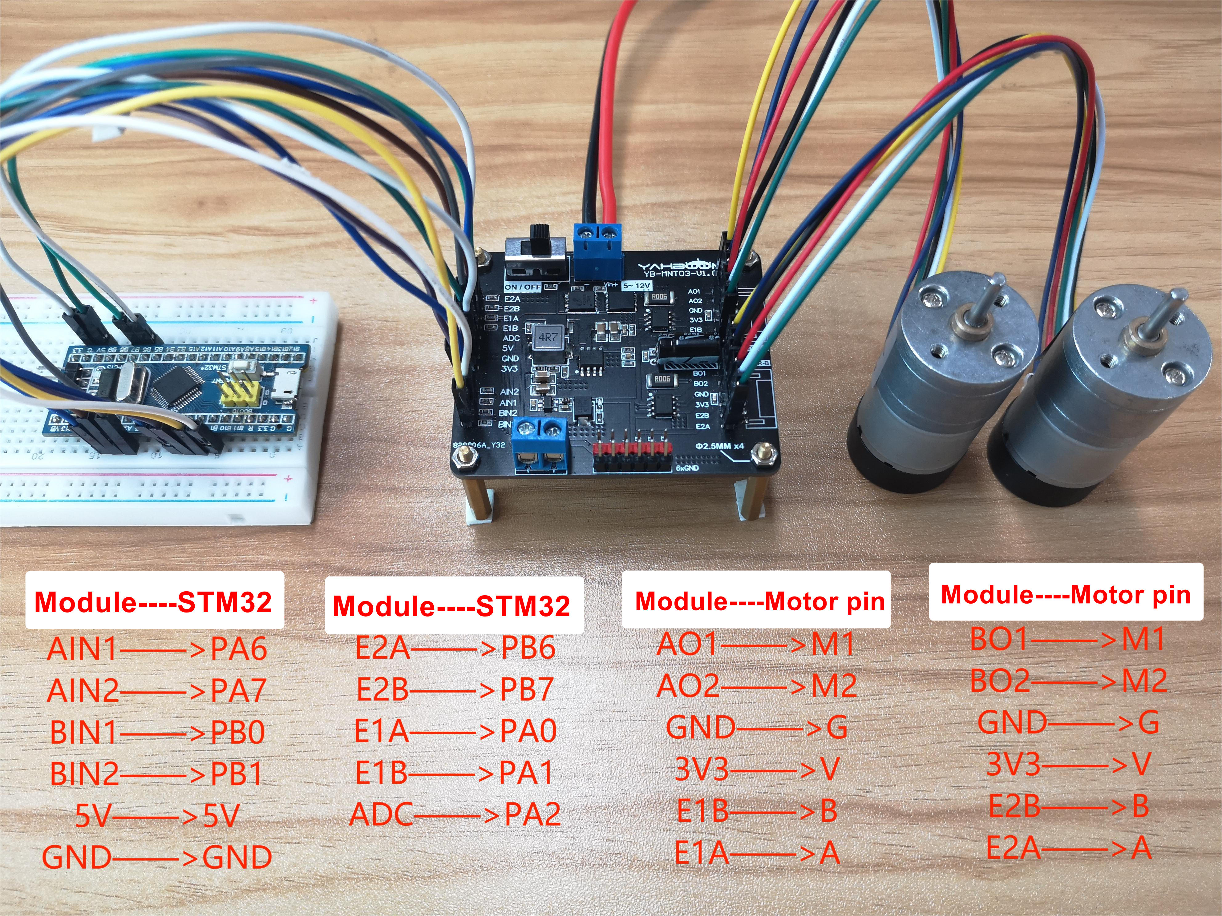
Note: The motor interface wire sequence of the dual motor drive board should correspond to the motor pin! Otherwise, the motor drive plate will be damaged
Note: The motor interface wire sequence of the dual motor drive board.
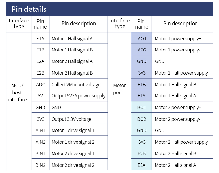
2. Code
x
int main(void) { u16 encoder_A,encoder_B; int Velocity_PWM1,Velocity_PWM2; u16 adcx; float vcc; SystemInit(); //Configure the system clock as 72Mhz delay_init(); //Delay function initialization uart_init(9600); //Serial port initialization adc_Init(); //ADC1 initialization PWM_Int(7199,0); //Initialize pwm output72000 000 /7199+1=10000 Encoder_Init_Tim2(); Encoder_Init_Tim4(); while(1) {// moto(0); //moto=0Forward rotation// moto(1); //moto=1Reversal rotation
adcx=Get_adc_Average(ADC_Channel_2,10); //Get the value of ADC vcc=(float)adcx*(3.3*11/4096); //Find the current voltage encoder_A=Read_Encoder(2); encoder_B=Read_Encoder(4); //Read encoder value Velocity_PWM1=Velocity_A(encoder_A); Velocity_PWM2=Velocity_B(encoder_B); Set_PWM(Velocity_PWM1,Velocity_PWM2); printf("µ±Ç°µçѹ=%6.2f V Encoder_A = %d Encoder_B=%d\r\n",vcc,encoder_A,encoder_B);//Print the current working voltage and speed } }
3.Experimental result
Write the code into the stm32 core board, the motor starts start to rotate.
Open the serial port software such as the serial port debugging assistant, set the baud rate to 9600, and you can see the current voltage value of the serial port output, and the speed of the encoded value of motor.