Welcome to AT8236 2-Channel Motor Driver Module repository
2.4 For RaspberryPi Pico
RaspberryPi Pico
1. Preparation
Connect the motor drive board and Raspberry Pi Pico according to the wiring diagram, connect the battery to the power input interface on motor drive module.

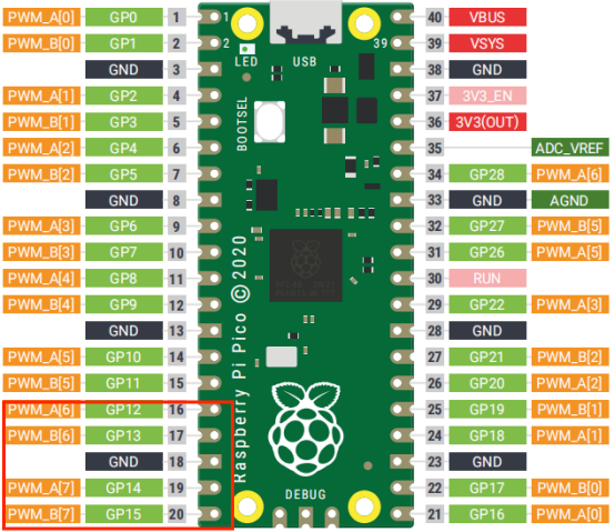
Note: The motor interface wire sequence of the dual motor drive board should correspond to the motor pin! Otherwise, the motor drive plate will be damaged.
Note: The motor interface wire sequence of the dual motor drive board.
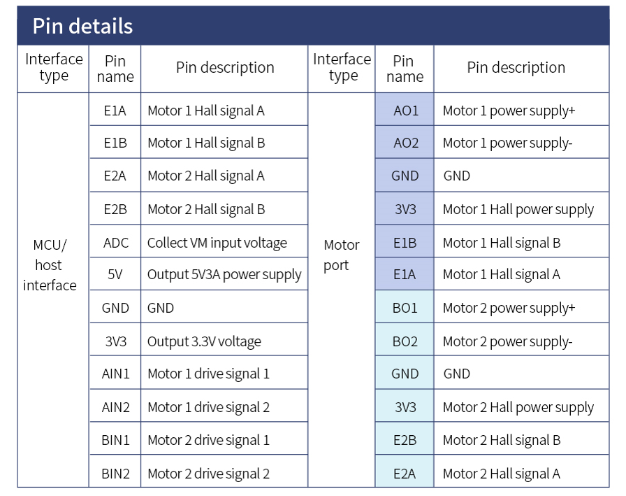
2. Code
ximport utime #Import Libraryfrom machine import Pin, PWM AIN1 = PWM(Pin(12)) #Set pinAIN2 = PWM(Pin(13))BIN1 = PWM(Pin(14))BIN2 = PWM(Pin(15))AIN1.freq(500)#Set AIN1 frequencyAIN2.freq(500)#Set frequencyBIN1.freq(500)#Set frequencyBIN2.freq(500)#Set frequency#Set duty cycle PWM_PulseWidth[i]/65535(i=0~4):100%,75%,50%,25%,0%#PWM_PulseWidth= [65535,49151,32767,16383,0]def forward(i): AIN1.duty_u16(i)#The motor rotates according to the set duty ratio AIN2.duty_u16(0) BIN1.duty_u16(i) BIN2.duty_u16(0)def stop(): #Motor stop AIN1.duty_u16(0) AIN2.duty_u16(0) BIN1.duty_u16(0) BIN2.duty_u16(0)def test(): #Test function, set the duty cycle to 49151, that is, 75%. Customers can set it according to their needs forward(49151) utime.sleep(4) stop()
test()#Run the test program, and the drive motor stops after 4s
3. Experimental result
Download the program to Raspberry Pi Pico. The motor starts to rotate for 4s, and then stops rotating.