Welcome to AT8236 2-Channel Motor Driver Module repository
2.2 For Arduino
Arduino uno R3
1.Preparation
Connect the motor drive board and Arduino UNO according to the wiring diagram, connect the battery to the power input interface on motor drive module.
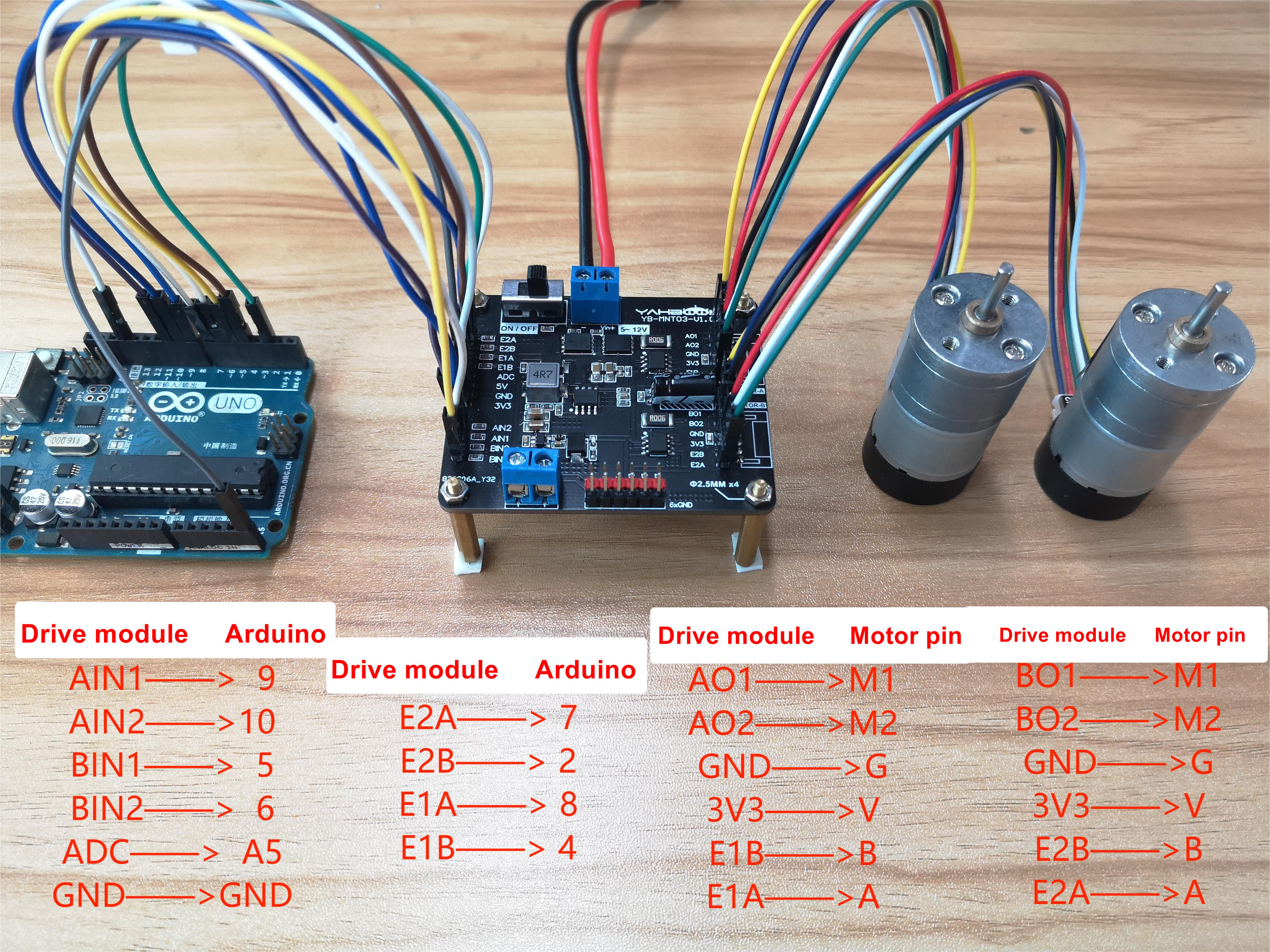
Note: The motor interface wire sequence of the dual motor drive board should correspond to the motor pin! Otherwise, the motor drive plate will be damaged
Note: The motor interface wire sequence of the dual motor drive board.
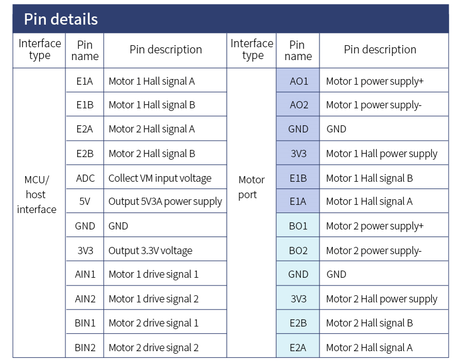
2.Code
x//External interrupt
/////////////////////////// Wiring method of this routine///////////////////////////// ArduinoUNOpin ------ AT8236module// Pin5 --- BIN1// Pin6 --- BIN2// Pin9 --- AIN1// Pin10 --- AIN2// PinA5 --- ADC// Pin8 --- E1A// Pin4 --- E1B// Pin7 --- E2A// Pin2 --- E2B// GND --- GND
/////////PWM Output pin//////////Analog pin reading power supply voltage
/////////Encoder pin//////////Encoder acquisition pins: 2 for each channel, 4 in total
double V; //Store voltage variableunsigned long TimeA=0;unsigned long EncoderTime=0;bool EncoderFlag=1;bool Mode=0;unsigned char LED_Count;volatile long Velocity_L, Velocity_R ; //Left and right wheel encoder datafloat Velocity_Left, Velocity_Right = 0; //Left and right wheel speedint delayShow=0;unsigned long TimeB=0;bool MotorFlag=1;bool TimeFlag=1;
//The default PWM value can be set directly through the serial port for different speedsint putPWM = 255;
void setup() { // put your setup code here, to run once: //PWMpin pinMode(AIN1, OUTPUT); pinMode(AIN2, OUTPUT); pinMode(BIN1, OUTPUT); pinMode(BIN2, OUTPUT);
//LEDpin pinMode(13, OUTPUT);
//Analog input pin pinMode(Voltage,INPUT); //Initialize as input
//Encoder pin pinMode(ENCODER_L, INPUT); pinMode(DIRECTION_L, INPUT); pinMode(ENCODER_R, INPUT); pinMode(DIRECTION_R, INPUT);
attachInterrupt(0, READ_ENCODER_R, CHANGE); //Enable external interrupt encoder interface 1 attachPinChangeInterrupt(4, READ_ENCODER_L, CHANGE); //Enable external interrupt encoder interface 2
//The PWM pin is set to zero to ensure that the motor does not rotate randomly. The parameter range is 0~255255, which is the full amplitude duty cycle analogWrite(AIN1, 0); analogWrite(AIN2, 0); analogWrite(BIN1, 0); analogWrite(BIN2, 0);
//Initialize serial port for outputting battery voltage Serial.begin(9600); }
//Set the PWM value of motor A, the range is - 255~255, where 0~255 corresponds to the duty ratio of 0~100, and a negative number means the motor is reversedvoid Set_PWMA(int pwm){ if(pwm>0) { analogWrite(AIN1, 255); analogWrite(AIN2, 255-pwm); } else { analogWrite(AIN2, 255); analogWrite(AIN1, 255+pwm); }}
//Set the PWM value of motor B, the range is - 255~255, where 0~255 corresponds to duty cycle 0~100, and a negative number indicates the motor is in reverse directionvoid Set_PWMB(int pwm){ if(pwm>0) { analogWrite(BIN1, 255); analogWrite(BIN2, 255-pwm); } else { analogWrite(BIN2, 255); analogWrite(BIN1, 255+pwm); }}
/*****Function function: external interrupt reads encoder data and has double frequency function. Note that external interrupt is triggered by jump edge********/void READ_ENCODER_L() { if (digitalRead(ENCODER_L) == LOW) { //If it is the interruption triggered by the falling edge if (digitalRead(DIRECTION_L) == LOW) Velocity_L--; //Determine direction according to another phase level else Velocity_L++; } else { //If it is an interruption triggered by the rising edge if (digitalRead(DIRECTION_L) == LOW) Velocity_L++; //Determine direction according to another phase level else Velocity_L--; }}/*****Function function: external interrupt reads encoder data and has double frequency function. Note that external interrupt is triggered by jump edge********/void READ_ENCODER_R() { if (digitalRead(ENCODER_R) == LOW) { //If it is the interruption triggered by the falling edge if (digitalRead(DIRECTION_R) == LOW) Velocity_R++;//Determine direction according to another phase level else Velocity_R--; } else { //If it is an interruption triggered by the rising edge if (digitalRead(DIRECTION_R) == LOW) Velocity_R--; //Determine direction according to another phase level else Velocity_R++; }}
void loop() {
// put your main code here, to run repeatedly: TimeA = millis(); //Get boot time
//Record timestamp if(EncoderFlag) EncoderFlag=0,EncoderTime = TimeA; if(TimeFlag) TimeFlag=0,TimeB = TimeA;
//Serial port changes PWM value to change motor speed if(Serial.available()) { int getInt = Serial.parseInt(); //Resolve the integer in the serial port data if(getInt>255) getInt=255; if(getInt<-255) getInt=-255; putPWM = getInt; }
//Change the rotation direction of the motor once every 4 seconds if(TimeA-TimeB>3999) TimeFlag=1,MotorFlag=!MotorFlag; if(MotorFlag)Set_PWMA(putPWM),Set_PWMB(putPWM); else Set_PWMA(-putPWM),Set_PWMB(-putPWM);
//LED flashes for 1 second if(LED_Count==99) LED_Count=0,Mode=!Mode, digitalWrite(13,Mode); //Read encoder data once in 10ms if(TimeA-EncoderTime>9) { EncoderFlag=1; Velocity_Left = Velocity_L; Velocity_L = 0; //Read the data of the left wheel encoder and clear it to zero. This is the speed obtained by measuring the speed (number of pulses per unit time) with M method. Velocity_Right = Velocity_R; Velocity_R = 0; //Read the right wheel encoder data and clear it
Velocity_Left = (Velocity_Left/780.0f)*100*60; Velocity_Right = (Velocity_Right/780.0f)*100*60;
delayShow++; LED_Count++;
//Display data once in 50ms if(delayShow==50) { delayShow=0; Serial.print("Velocity_L = "); Serial.print(Velocity_Left); Serial.println(" R/M"); Serial.print("Velocity_R = "); Serial.print(Velocity_Right); Serial.println(" R/M"); V=analogRead(Voltage); //Read analog quantity of analog pin A0 Serial.print("Input voltage = "); Serial.print(V*0.05371); //Convert analog quantity and output through serial port Serial.println("V");
Serial.print("PWM = "); Serial.println(putPWM); Serial.println(""); Serial.println(""); } }}
3.Experimental result
Connect the arduino to the computer through the USB data cable, upload the program to the Arduino board, motor will start to rotate.
Open the serial port monitor of the Arduino IDE and set the baud rate of 9600. You can see that the serial port displays the positive and negative speed of the two motors, the input voltage value, and the current pwm speed regulation.