Welcome to Motor with Encoder repository
For ESP32
Drive motor and read encoder-IIC
1.1 Explanation
Please read 《0. Motor introduction and usage》first to understand the motor parameters, wiring method, and power supply voltage you are currently using. To avoid improper operation and damage to the driver board or motor.
I2C and serial communication cannot be shared, only one can be selected.
This course uses the YahboomESP32 image transmission module lite version.
If you use other ESP32-S3 boards, you need to modify the pin settings in the program according to your board pin situation.
Use ESP-IDF 5.4.0 version to compile the project.
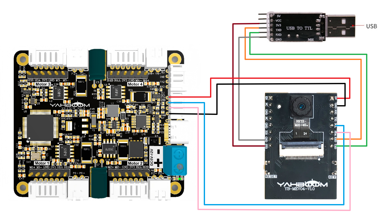
Hardware wiring:
| Motor | 4-channel motor drive board(Motor) |
|---|---|
| M2 | M- |
| V | 3V3 |
| A | H1A |
| B | H1B |
| G | GND |
| M1 | M+ |
| 4-channel motor drive board | ESP32-S3 |
|---|---|
| SDA | SDA |
| SCL | SCL |
| GND | GND |
| 5V | 5V |
USB to TTL serial port module needs to be connected, mainly for printing data.
When using the Yahboom ESP32 image transmission module lite version, the 3V3 of the USB to TTL serial port module must be replaced with 5V and connected to the 5V on the ESP32 board to write the program normally.
After the program is written, it can be switched back to 3V3.
| USB TO TTL | ESP32S3 |
|---|---|
| 3V3 | 3V3 |
| TXD | RX0 |
| RXD | TX0 |
| GND | GND |
Serial port configuration: Baud rate 115200, no parity check, no hardware flow control, 1 stop bit
Note: The serial port here is used to print data on the serial port assistant, not for communication with the driver board
1.2 Code analysis
// SCL// SDAThis code is defined in the file i2c_module.h.
If you need to change the pin for I2C communication, you can modify the number here.
x// 1:接收总的编码器数据 2:接收实时的编码器 1: Receive total encoder data 2: Receive real-time encoder data
//1:520电机 2:310电机 3:测速码盘TT电机 4:TT直流减速电机 5:L型520电机 //1:520 motor 2:310 motor 3:speed code disc TT motor 4:TT DC reduction motor 5:L type 520 motorUPLOAD_DATA: used to set the data of the motor encoder. Set 1 to the total number of encoder pulses and 2 to the real-time pulse data of 10ms.
MOTOR_TYPE: used to set the type of motor used. Just modify the corresponding numbers according to the comments according to the motor you are currently using. You don’t need to modify the rest of the code.
If you need to drive the motor and observe the data, just modify the two numbers at the beginning of the program. No changes are required to the rest of the code.
xxxxxxxxxx Set_motor_type(1);//配置电机类型 Configure motor type delay(100); Set_Pluse_Phase(30);//配置减速比 查电机手册得出 Configure the reduction ratio. Check the motor manual to find out delay(100); Set_Pluse_line(11);//配置磁环线 查电机手册得出 Configure the magnetic ring wire. Check the motor manual to get the result. delay(100); Set_Wheel_dis(67.00);//配置轮子直径,测量得出 Configure the wheel diameter and measure it delay(100); Set_motor_deadzone(1900);//配置电机死区,实验得出 Configure the motor dead zone, and the experiment shows delay(100); Set_motor_type(2); delay(100); Set_Pluse_Phase(20); delay(100); Set_Pluse_line(13); delay(100); Set_Wheel_dis(48.00); delay(100); Set_motor_deadzone(1600); delay(100); Set_motor_type(3); delay(100); Set_Pluse_Phase(45); delay(100); Set_Pluse_line(13); delay(100); Set_Wheel_dis(68.00); delay(100); Set_motor_deadzone(1250); delay(100); Set_motor_type(4); delay(100); Set_Pluse_Phase(48); delay(100); Set_motor_deadzone(1000); delay(100); Set_motor_type(1); delay(100); Set_Pluse_Phase(40); delay(100); Set_Pluse_line(11); delay(100); Set_Wheel_dis(67.00); delay(100); Set_motor_deadzone(1900); delay(100);
This is used to store the parameters of the Yahboom motor. By modifying the MOTOR_TYPE parameter above, one-click configuration can be achieved.
In normally, do not modify the code here when using the Yahboom motor.
If you are using your own motor, or if a certain data needs to be modified according to your needs, you can check the course《1.2 Control command》 to understand the specific meaning of each command.
xxxxxxxxxxwhile(1) { for(i=0;i<100;i++) { // 根据电机类型选择控制方式 | Select control mode by motor type control_pwm(i*20,i*20,i*20,i*20);// PWM控制模式 | PWM control control_speed(i*10,i*10,i*10,i*10);// 速度控制模式 | Speed control delay_ms(100); Read_ALL_Enconder(); printf("M1:%d\t M2:%d\t M3:%d\t M4:%d\t \r\n",Encoder_Now[0],Encoder_Now[1],Encoder_Now[2],Encoder_Now[3]); Read_10_Enconder(); printf("M1:%d\t M2:%d\t M3:%d\t M4:%d\t \r\n",Encoder_Offset[0],Encoder_Offset[1],Encoder_Offset[2],Encoder_Offset[3]);
}
}In the main program loop, the speed of the four motors will be slowly increased from 0 to 1000. If the motor type is 4, that is, the motor without encoder, the PWM of the motor is directly controlled.
At the same time, the data sent by the driver board is read and printed out.
xxxxxxxxxx//读取相对时间的编码器的数据 10ms的   Read the data of the encoder of relative time 10msvoid Read_10_Enconder(void){    static int8_t buf[2];            //M1电机编码器的数据    M1 motor encoder data    i2cRead(Motor_model_ADDR, READ_TEN_M1Enconer_REG, 2, buf);    Encoder_Offset[0] = buf[0]<<8|buf[1];         //M2电机编码器的数据    M2 motor encoder data    i2cRead(Motor_model_ADDR, READ_TEN_M2Enconer_REG, 2, buf);    Encoder_Offset[1] = buf[0]<<8|buf[1];        //M3电机编码器的数据    M3 motor encoder data    i2cRead(Motor_model_ADDR, READ_TEN_M3Enconer_REG, 2, buf);    Encoder_Offset[2] = buf[0]<<8|buf[1];        //M4电机编码器的数据    M4 motor encoder data    i2cRead(Motor_model_ADDR, READ_TEN_M4Enconer_REG, 2, buf);    Encoder_Offset[3] = buf[0]<<8|buf[1];    }
//读取电机转动的编码器数据  Read the encoder data of the motor rotationvoid Read_ALL_Enconder(void){    static uint8_t buf[2];    static uint8_t buf2[2];        //M1电机编码器的数据    M1 motor encoder data    i2cRead(Motor_model_ADDR, READ_ALLHigh_M1_REG, 2, buf);    i2cRead(Motor_model_ADDR, READ_ALLLOW_M1_REG, 2, buf2);        Encoder_Now[0] = buf[0]<<24|buf[1]<<16|buf2[0]<<8|buf2[1];         //M2电机编码器的数据    M2 motor encoder data    i2cRead(Motor_model_ADDR, READ_ALLHigh_M2_REG, 2, buf);    i2cRead(Motor_model_ADDR, READ_ALLLOW_M2_REG, 2, buf2);    Encoder_Now[1] = buf[0]<<24|buf[1]<<16|buf2[0]<<8|buf2[1];        //M3电机编码器的数据    M3 motor encoder data    i2cRead(Motor_model_ADDR, READ_ALLHigh_M3_REG, 2, buf);    i2cRead(Motor_model_ADDR, READ_ALLLOW_M3_REG, 2, buf2);    Encoder_Now[2] = buf[0]<<24|buf[1]<<16|buf2[0]<<8|buf2[1];            //M4电机编码器的数据    M4 motor encoder data    i2cRead(Motor_model_ADDR, READ_ALLHigh_M4_REG, 2, buf);    i2cRead(Motor_model_ADDR, READ_ALLLOW_M4_REG, 2, buf2);    Encoder_Now[3] = buf[0]<<24|buf[1]<<16|buf2[0]<<8|buf2[1];    }
After getting the data from the driver board, it is shifted, and the shift is required to get the correct data.
1.3 Experimental phenomenon
After the wiring is correct, write the program into the mainboard. After powering on again, you can see that the motor will gradually speed up, then stop, and repeat.
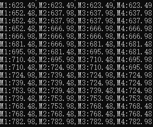
At the same time, you can see the motor value constantly changing in the serial monitor.