Welcome to STM32F103RCT6 Core board repository
4.Read IMU raw data
Read IMU raw data
Read IMU raw data1.IMU Introduction2.IMU principle3.Brief analysis of IMU driver codeExperimental effect
1.IMU Introduction
The IMU used on the board is the ICM-40607 model, which is the upgraded version of MPU6050. However, compared with MPU6050, it lacks the function of four-element conversion of Euler angle. You need to write this part of function yourself. This tutorial does not provide the functions of this part. Interested students can learn from CSDN by themselves. ICM-40607: gyroscope included in it is used to measure angular velocity; Accelerometer, used to measure linear velocity.
2.IMU principle
According to the manual and schematic diagram
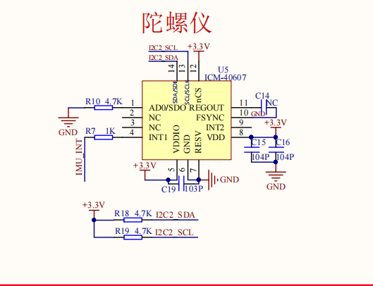
The following results can be obtained:
- IMU can be controlled by I2C protocol or SPI protocol, but the schematic diagram shows that it can only be controlled by I2C, and this experiment uses the communication mode of software I2C.
- The accelerometers and gyroscopes of the IMU on board are set with corresponding ranges through register configuration.
- The I2C address of IMU is related to the level of AD0 pin. The address of AD0=0: I2C is 0x68, and the address of AD0=1: I2C is 0x69
3.Brief analysis of IMU driver code
Initialize I2C communication
void i2c_Init(void){GPIO_InitTypeDef GPIO_InitStructure;RCC_APB2PeriphClockCmd(RCC_APB2Periph_GPIOB,ENABLE);//Enable peripheral IO PORTC clock firstGPIO_InitStructure.GPIO_Pin = GPIO_Pin_10|GPIO_Pin_11; // Port configurationGPIO_InitStructure.GPIO_Mode = GPIO_Mode_Out_PP; //Push-pull outputGPIO_InitStructure.GPIO_Speed = GPIO_Speed_50MHz; //IO port speed is 50MHzGPIO_Init(GPIOB, &GPIO_InitStructure); //Initialization according to the setting parameters GPIOGPIO_SetBits(GPIOB,GPIO_Pin_10|GPIO_Pin_11);}
I2C read and write function
xxxxxxxxxxstatic int myi2c_write(struct inv_icm406xx_serif * serif, uint8_t reg, const uint8_t * wbuffer, uint32_t wlen){i2c_Write(ICM_40607_ADDR, reg, wlen, (uint8_t *)wbuffer);return 0;}•static int myi2c_read(struct inv_icm406xx_serif * serif, uint8_t reg, uint8_t * rbuffer, uint32_t rlen){i2c_Read(ICM_40607_ADDR, reg, rlen, rbuffer);return 0;}
Initialize ICM40607 chip
xint8_t icm40607_init(void){int rc = 0;uint8_t who_am_i = 0x00;struct inv_icm406xx_serif icm406xx_serif;/* Initialize MCU hardware */icm406xx_serif.context = 0; /* no need */icm406xx_serif.read_reg = myi2c_read;icm406xx_serif.write_reg = myi2c_write;icm406xx_serif.max_read = 1024*32; /* maximum number of bytes allowed per serial read */icm406xx_serif.max_write = 1024*32; /* maximum number of bytes allowed per serial write */icm406xx_serif.serif_type = ICM406XX_UI_I2C;/* Initialize Icm406xx */rc = inv_icm406xx_init(&icm_driver, &icm406xx_serif, NULL);if(rc != INV_ERROR_SUCCESS) {printf("icm40607 init fail!\n");return rc;}/* Disable fifo usage, data will be read from sensors registers*/rc |= inv_icm406xx_configure_fifo(&icm_driver, INV_ICM406XX_FIFO_DISABLED);if(rc != INV_ERROR_SUCCESS) {printf("icm40607 configure fail!\n");return rc;}icm_driver.sensor_event_cb = event_cb;rc = inv_icm406xx_get_who_am_i(&icm_driver, &who_am_i);if(rc != INV_ERROR_SUCCESS) {printf("I2C Get who am i error\n");return -2;}//icm_I2C_read(MPUREG_WHO_AM_I, &who_am_i, 1);if(who_am_i != ICM_WHOAMI) {printf("who am i ID error: 0x%02X\n", who_am_i);return -3;}//成功打印icm id号printf("who_am_i = 0x%02X \n",who_am_i);//自检RunSelfTest();/* Configure Icm406xx *//* /!\ In this example, the data output frequency will be the faster between Accel and Gyro odr */rc = ConfigureInvDevice((uint8_t )IS_LOW_NOISE_MODE,ICM406XX_ACCEL_CONFIG0_FS_SEL_8g,ICM406XX_GYRO_CONFIG0_FS_SEL_500dps,ICM406XX_ACCEL_CONFIG0_ODR_100_HZ,ICM406XX_GYRO_CONFIG0_ODR_100_HZ,(uint8_t )USE_CLK_IN);return rc;}
Read raw data from the ICM40607 register.
xxxxxxxxxxint GetDataFromInvDevice(inv_icm406xx_sensor_event_t* evt){if(evt != NULL){event = evt;return inv_icm406xx_get_data_from_registers(&icm_driver);}else{return -1;}}
xxxxxxxxxxint inv_icm406xx_get_data_from_registers(struct inv_icm406xx * s){int status = 0;uint8_t int_status;uint8_t temperature[2];uint8_t accel[ACCEL_DATA_SIZE];uint8_t gyro[GYRO_DATA_SIZE];inv_icm406xx_sensor_event_t event;/* Ensure data ready status bit is set */status |= inv_icm406xx_read_reg(s, MPUREG_INT_STATUS, 1, &int_status);if(status)return status;if(int_status & BIT_INT_STATUS_DRDY) {status = inv_icm406xx_read_reg(s, MPUREG_TEMP_DATA0_UI, TEMP_DATA_SIZE, temperature);inv_icm406xx_format_data(s->endianess_data, temperature, (uint16_t *)&event.temperature);status |= inv_icm406xx_read_reg(s, MPUREG_ACCEL_DATA_X0_UI, ACCEL_DATA_SIZE, accel);inv_icm406xx_format_data(s->endianess_data, &accel[0], (uint16_t *)&event.accel[0]);inv_icm406xx_format_data(s->endianess_data, &accel[2], (uint16_t *)&event.accel[1]);inv_icm406xx_format_data(s->endianess_data, &accel[4], (uint16_t *)&event.accel[2]);status |= inv_icm406xx_read_reg(s, MPUREG_GYRO_DATA_X0_UI, GYRO_DATA_SIZE, gyro);inv_icm406xx_format_data(s->endianess_data, &gyro[0], (uint16_t *)&event.gyro[0]);inv_icm406xx_format_data(s->endianess_data, &gyro[2], (uint16_t *)&event.gyro[1]);inv_icm406xx_format_data(s->endianess_data, &gyro[4], (uint16_t *)&event.gyro[2]);/* call sensor event callback */if(s->sensor_event_cb)s->sensor_event_cb(&event);/* Device interrupts delayed when communicating with other slaves connected to same bus* Semi-Write to release interrupt in I2C*/if((s->transport.serif.serif_type == ICM406XX_UI_I2C) || (s->transport.serif.serif_type == ICM406XX_UI_I3C)) {uint8_t data = 0;status |= inv_icm406xx_write_reg(s, MPUREG_WHO_AM_I, 1, &data);}}/*else: Data Ready was not set*/return status;}
Read data cycles and print to the serial assistant and display.
xxxxxxxxxxwhile (1){if (Key1_State(KEY_MODE_ONE_TIME)){LED = !LED;}GetDataFromInvDevice(&imu_event);#if GYRO_DATAval_x = imu_event.gyro[0];val_y = imu_event.gyro[1];val_z = imu_event.gyro[2];printf("gx=%d\t,gy=%d\t,gz=%d\n", val_x, val_y, val_z);#if LCD_SWITCHsprintf(buf_text, "gyroX =%d ", val_x);LCD_ShowString(10, 15, (u8 *)buf_text, BLACK, WHITE, 16, 0);sprintf(buf_text, "gyroY =%d ", val_y);LCD_ShowString(10, 30, (u8 *)buf_text, BLACK, WHITE, 16, 0);sprintf(buf_text, "gyroZ =%d ", val_z);LCD_ShowString(10, 45, (u8 *)buf_text, BLACK, WHITE, 16, 0);#endif#elif ACC_DATAval_x = imu_event.accel[0];val_y = imu_event.accel[1];val_z = imu_event.accel[2];printf("ax=%d\t,ay=%d\t,az=%d\n", val_x, val_y, val_z);#if LCD_SWITCHsprintf(buf_text, "accX =%d ", val_x);LCD_ShowString(10, 15, (u8 *)buf_text, BLACK, WHITE, 16, 0);sprintf(buf_text, "accY =%d ", val_y);LCD_ShowString(10, 30, (u8 *)buf_text, BLACK, WHITE, 16, 0);sprintf(buf_text, "accZ =%d ", val_z);LCD_ShowString(10, 45, (u8 *)buf_text, BLACK, WHITE, 16, 0);#endif#endifdelay_ms(100);}
Experimental effect
1.When it is detected that the IMU is not online, please press the reset key and power off to restart. The effect is as shown in the figure:
2.When the IMU is detected online and communication is performed, the LCD screen will display the accelerometer data, as shown in the figure: At this time, shake the development board and you can
Note: The program defaults to display the accelerometer value. If you need to display the gyroscope value, please find GYRO_DATA in the main.c file of the program and modify the macro definition value to 1.

Since there is an error in each IMU component, in a static state, all values will not be zero, as long as the stability and feedback are accurate.