Welcome to STM32F103RCT6 Core board repository
9. Serial communication
serial communication
1、 Learning objectives
1.Learn the basic use of the STM32 motherboard serial port.
2.Understand the basic knowledge of serial communication.
USART introduction of STM32F1:
Serial communication refers to a communication method in which peripherals and computers transmit data bit by bit through data signal lines, ground wires, etc., belonging to serial communication.
USART is a universal synchronous asynchronous transceiver that can flexibly exchange full-duplex data with external devices, meeting the requirements of external devices for the industry standard NRZ asynchronous serial data format. UART is a universal asynchronous transceiver, which cuts out the synchronous communication function based on USART. Synchronization and asynchrony mainly depend on whether its clock needs to be provided externally. This chapter mainly uses USART, and the STM32F103C8T6 chip contains three USART peripherals. USART supports synchronous one-way communication and half duplex single line communication; It also supports LIN (Domain Interconnection Network), smart card protocols, and IrDA (Infrared Data Association) SIR ENDEC specifications, as well as modem operations (CTS/RTS). In addition, it also supports multiprocessor communication and DMA functions, enabling high-speed data communication using DMA. USART provides multiple baud rates through a decimal baud rate generator. The most common application of USART in STM32 is printf output debugging information. When we need to understand some variable data information within a program, we can use the printf output function to print this information to the serial port and display it on the assistant, which brings us great convenience in debugging the program.
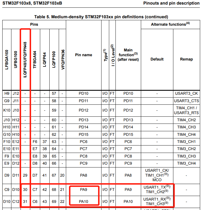
When using, the corresponding pin of each serial port can be found in the STM32 data manual.
2、 Hardware construction
Due to the built-in CH340 serial port circuit on the core board, serial communication can be achieved directly through a USB cable, without the need for an external USB to TTL module.
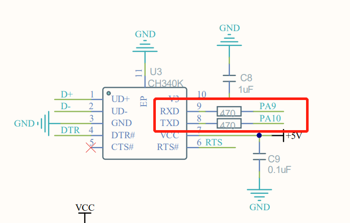
Partial circuit diagram of CH340
3、 Program analysis
Serial port initialization code:
xvoid USART1_init(u32 baudrate){ GPIO_InitTypeDef GPIO_InitStructure; USART_InitTypeDef USART_InitStructure; NVIC_InitTypeDef NVIC_InitStructure; RCC_APB2PeriphClockCmd(RCC_APB2Periph_USART1 | RCC_APB2Periph_GPIOA, ENABLE); GPIO_InitStructure.GPIO_Pin = GPIO_Pin_9; GPIO_InitStructure.GPIO_Mode = GPIO_Mode_AF_PP; GPIO_InitStructure.GPIO_Speed = GPIO_Speed_50MHz; GPIO_Init(GPIOA, &GPIO_InitStructure); GPIO_InitStructure.GPIO_Pin = GPIO_Pin_10; GPIO_InitStructure.GPIO_Mode = GPIO_Mode_IN_FLOATING; GPIO_Init(GPIOA, &GPIO_InitStructure); USART_InitStructure.USART_BaudRate = baudrate; USART_InitStructure.USART_WordLength = USART_WordLength_8b; USART_InitStructure.USART_StopBits = USART_StopBits_1; USART_InitStructure.USART_Parity = USART_Parity_No ; USART_InitStructure.USART_HardwareFlowControl = USART_HardwareFlowControl_None; USART_InitStructure.USART_Mode = USART_Mode_Rx | USART_Mode_Tx; USART_Init(USART1, &USART_InitStructure); USART_ITConfig(USART1, USART_IT_TXE, DISABLE); USART_ITConfig(USART1, USART_IT_RXNE, ENABLE); USART_ClearFlag(USART1,USART_FLAG_TC); USART_Cmd(USART1, ENABLE); NVIC_InitStructure.NVIC_IRQChannel = USART1_IRQn; NVIC_InitStructure.NVIC_IRQChannelPreemptionPriority = 3; NVIC_InitStructure.NVIC_IRQChannelSubPriority = 3; NVIC_InitStructure.NVIC_IRQChannelCmd = ENABLE; NVIC_Init(&NVIC_InitStructure);}At USART1_ In the Init() function, first enable the USART1 serial port and port clock, and initialize GPIO as a multiplexing function. Second, configure the serial port structure USART_ InitTypeDef enables the serial port and enables receiving interrupts. To prevent the impact of the serial port sending status flag, we clear the serial port status flag (TC), and finally configure the corresponding NVIC and enable the corresponding interrupt channel. We set the preemption priority of USART1 to 3 and the response priority to 3.
Serial port interrupt code:
xxxxxxxxxx//Serial port interrupt service functionvoid USART1_IRQHandler(void){ uint8_t Rx1_Temp = 0; if (USART_GetITStatus(USART1, USART_IT_RXNE) != RESET) { Rx1_Temp = USART_ReceiveData(USART1); USART1_Send_U8(Rx1_Temp); }}To confirm whether a receive interrupt has occurred in USART1, the read serial port interrupt status flag bit function USART is called_ GetITStatus: If a receive interrupt event does occur, the statement in if will be executed to store the data received by the serial port in the variable r, and then it will be sent through the serial port through USART_ The GetFlagStatus function reads the serial port status flag. If the data transmission is completed, the while loop statement exits and the transmission completion status flag bit USART is cleared_ FLAG_ TC。
Main function code:
xxxxxxxxxxint main(void){ u8 i; BSP_init(); while(1) { LED =!LED; delay_ms(200); }}The main function is very simple. First, call the previously written hardware initialization functions, including SysTick system clock, interrupt grouping, LED initialization, and so on. Then call the USART1 initialization function we wrote earlier. Here we set the serial communication baud rate to 9600. Finally, enter the while loop statement and keep flashing the D1 indication interval of 200ms. If a receive interrupt event occurs, it will enter interrupt execution and return to the main function to continue running after execution.
4、Experimental phenomenon
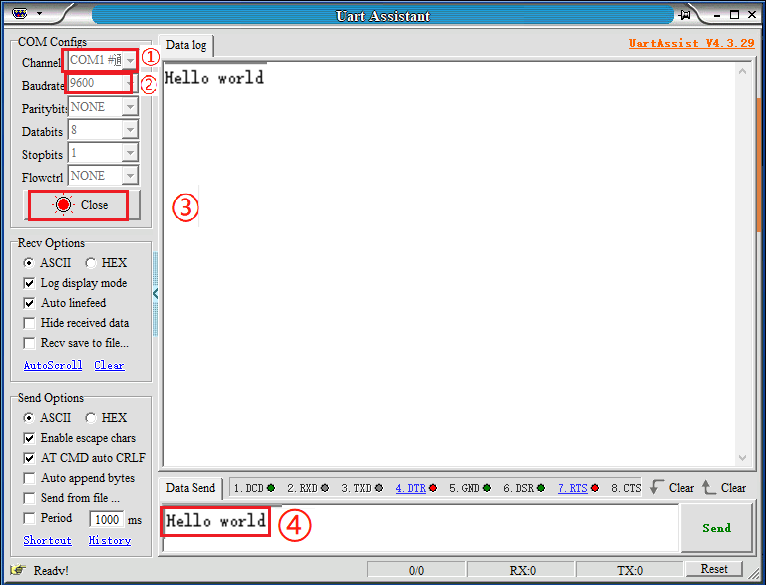
After the program is downloaded, the LED flashes and the serial port assistant is configured as shown in the following figure. You can view the returned transmission content in the serial port assistant receiving window.
Note: The baud rate must be 9600, otherwise the content sent cannot be received.