Welcome to STM32F103RCT6 Core board repository
8. PWM Breathing Lamp Experiment
PWM Breathing Lamp Experiment
1、Learning objectives
1.Learn the principle of PWM breathing lamp.
2.The CH4 of the TIM4 outputs a PWM signal to control the LED indicator light from dark to light, and then from light to dark, similar to human breathing.
Introduction to PWM principle:
PWM is an abbreviation for Pulse Width Modulation, which means Pulse Width Modulation (PWM) in Chinese. It is a very effective technology that utilizes the digital output of a microprocessor to control analog circuits. Its advantages such as simple control, flexibility, and good dynamic response have made it the most widely used control method in power electronics technology. Its application fields include measurement, communication, power control and conversion, motor control, servo control, dimming, switching power supplies, and even some audio amplifiers, Therefore, learning PWM has very important practical significance.
In fact, we can also understand that PWM is a method of digitally encoding analog signal levels. Through the use of high-resolution counters, the duty cycle of the square wave is modulated to encode the level of a specific analog signal. The PWM signal is still digital because at any given moment, the full amplitude DC power supply is either completely ON or completely OFF. The voltage or current source is applied to the analog load in an ON or OFF repetitive pulse sequence. When the DC power supply is applied to the load, when it is turned on, it is when the power supply is turned off. As long as the bandwidth is sufficient, any analog value can be encoded using PWM.
2、Hardware construction
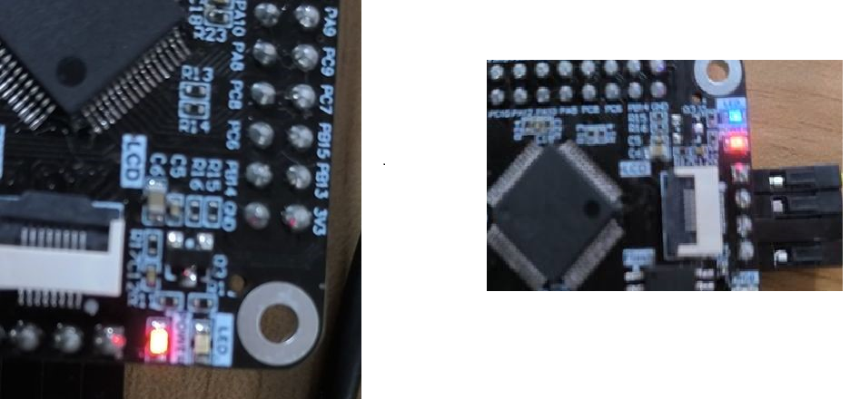
The timer pin used in this experiment is PB9, and the corresponding timer channel is TIM4_ For CH4, because the PB9 pin does not have an LED light, in order to observe the effect of the breathing light, we connect the PB9 and PB4 with a DuPont cable and directly use the LED light on the board.
Note: 1. After successfully downloading the program, wire the pins; DuPont line needs to be purchased separately.

Wiring reference diagram
Program analysis
The PWM output frequency is constant, changing the value in the CCR register, and a change in this value will result in a change in the PWM output signal duty cycle. The duty cycle is actually the ratio of the high level time to the cycle within a cycle, and changing this ratio can control the time for the io pin to output the high level and low level. Therefore, the control of the LED breathing lamp can be achieved by outputting a PWM signal through the CH4 of the TIM4.
LED initialization code:
void LED_Init(){ GPIO_InitTypeDef GPIO_InitStructure; RCC_APB2PeriphClockCmd(LED_PORT_RCC,ENABLE); GPIO_InitStructure.GPIO_Pin=LED_PIN; GPIO_InitStructure.GPIO_Mode=GPIO_Mode_IN_FLOATING; GPIO_InitStructure.GPIO_Speed=GPIO_Speed_50MHz; GPIO_Init(LED_PORT,&GPIO_InitStructure); }PWM initialization code:
xxxxxxxxxxvoid TIM4_CH4_PWM_Init(u16 per,u16 psc){ TIM_TimeBaseInitTypeDef TIM_TimeBaseInitStructure; TIM_OCInitTypeDef TIM_OCInitStructure; GPIO_InitTypeDef GPIO_InitStructure; /* Turn on the clock */ RCC_APB2PeriphClockCmd(RCC_APB2Periph_GPIOB,ENABLE); RCC_APB1PeriphClockCmd(RCC_APB1Periph_TIM4,ENABLE); //RCC_APB2PeriphClockCmd(RCC_APB2Periph_AFIO,ENABLE); /* Configure the mode and IO port of GPIO */ GPIO_InitStructure.GPIO_Pin=GPIO_Pin_9; GPIO_InitStructure.GPIO_Speed=GPIO_Speed_50MHz; GPIO_InitStructure.GPIO_Mode=GPIO_Mode_AF_PP; GPIO_Init(GPIOB,&GPIO_InitStructure); //GPIO_PinRemapConfig(GPIO_FullRemap_TIM3,ENABLE); TIM_TimeBaseInitStructure.TIM_Period=per; //Auto Load Value TIM_TimeBaseInitStructure.TIM_Prescaler=psc; //division factor TIM_TimeBaseInitStructure.TIM_ClockDivision=TIM_CKD_DIV1; TIM_TimeBaseInitStructure.TIM_CounterMode=TIM_CounterMode_Up; //Set Up Count Mode TIM_TimeBaseInit(TIM4,&TIM_TimeBaseInitStructure); TIM_OCInitStructure.TIM_OCMode=TIM_OCMode_PWM1; TIM_OCInitStructure.TIM_OCPolarity=TIM_OCPolarity_Low; TIM_OCInitStructure.TIM_OutputState=TIM_OutputState_Enable; TIM_OC4Init(TIM4,&TIM_OCInitStructure); //Output comparison channel 4 initialization TIM_OC4PreloadConfig(TIM4,TIM_OCPreload_Enable); //Enable TIMx preload register on CCR1 TIM_ARRPreloadConfig(TIM4,ENABLE);//Enable preload register TIM_Cmd(TIM4,ENABLE); //Enable timer }Main function code:
xint main(){ u16 i=0; u8 fx=0; SysTick_Init(72); NVIC_PriorityGroupConfig(NVIC_PriorityGroup_2); LED_Init(); RCC_APB2PeriphClockCmd(RCC_APB2Periph_AFIO, ENABLE); GPIO_PinRemapConfig(GPIO_Remap_SWJ_JTAGDisable, ENABLE); TIM4_CH4_PWM_Init(500,72-1); //The frequency is 2 Kh while(1) { if(fx==0) { i++; if(i==500) { fx=1; } } else { i--; if(i==0) { fx=0; } } TIM_SetCompare4(TIM4,i); //The maximum i value can be taken as 499 because the maximum ARR value is 499 delay_ms(5); }}Experimental phenomenon
After downloading the program, we can see that the LED lights on the STM32 motherboard slowly turn off, showing a breathing light effect.