Welcome to 8-Channel Tracking Module repository
I2C method
arduino - I2C method
arduino - I2C methodExperimental preparationPurposeExperimental wiringExperimental steps and phenomenaExperimental source code
Experimental preparation
Arduino mainboard
8-channel line patrol module
Several Dupont cables
Adruino board needs to download the I2C communication source code provided in the document
Purpose
The content of this experiment is mainly to use the Arduino master to receive the data of the 8-channel line patrol module through I2C.
Experimental wiring
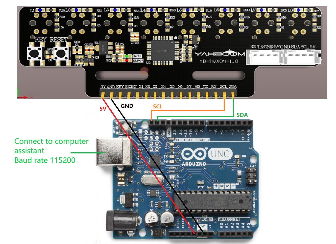
Adruino connected to the serial port assistant, directly use the program download port to connect
| adruino | 8-channel line patrol module |
|---|---|
| SDA | SDA |
| SCL | SCL |
| 5V | 5V |
| GND | GND |
As shown in the figure:
Experimental steps and phenomena
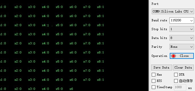
After connecting the wires, open the serial port assistant and you can see the numerical data of the infrared module. Set the baud rate to 115200. As shown below:
Experimental source code
xvoid loop() { byte data = 0; // Used to store read data Wire.beginTransmission(0x12); // The address of the I2C device Wire.write(0x30); // Register Address Wire.endTransmission(); delay(10); // Give the device enough time to process the request Wire.requestFrom(0x12, 1); // Request 1 byte of data while (Wire.available()) { data = Wire.read(); // Reading Data } x1 = (data>>7)&0x01; x2 = (data>>6)&0x01; x3 = (data>>5)&0x01; x4 = (data>>4)&0x01; x5 = (data>>3)&0x01; x6 = (data>>2)&0x01; x7 = (data>>1)&0x01; x8 = (data>>0)&0x01; sprintf(bufbuf,"x1:%d,x2:%d,x3:%d,x4:%d,x5:%d,x6:%d,x7:%d,x8:%d\r\n",x1,x2,x3,x4,x5,x6,x7,x8); Serial.println(bufbuf); delay(500);}
The source code obtains the data of the infrared probe by reading the register address 0x30 of the infrared module and prints it out through the serial port.