Welcome to 8-Channel Tracking Module repository
Serial Port method
Raspberry Pi - Serial Port Method
Raspberry Pi - Serial Port MethodExperimental preparationExperimental purposeExperimental wiringOpen the Raspberry Pi hard serial port (Raspberry Pi 5 does not require this step)Experimental steps and phenomenaExperimental source code
Experimental preparation
Raspberry Pi motherboard
8-channel line patrol module
Several Dupont cables
The Raspberry Pi board needs to download the serial communication source code provided in the document, and the Raspberry Pi system needs to open the serial communication interface through raspi-config
Experimental purpose
The content of this experiment is mainly to use the Raspberry Pi main control to receive the data of the 8-channel line patrol module through the serial port.
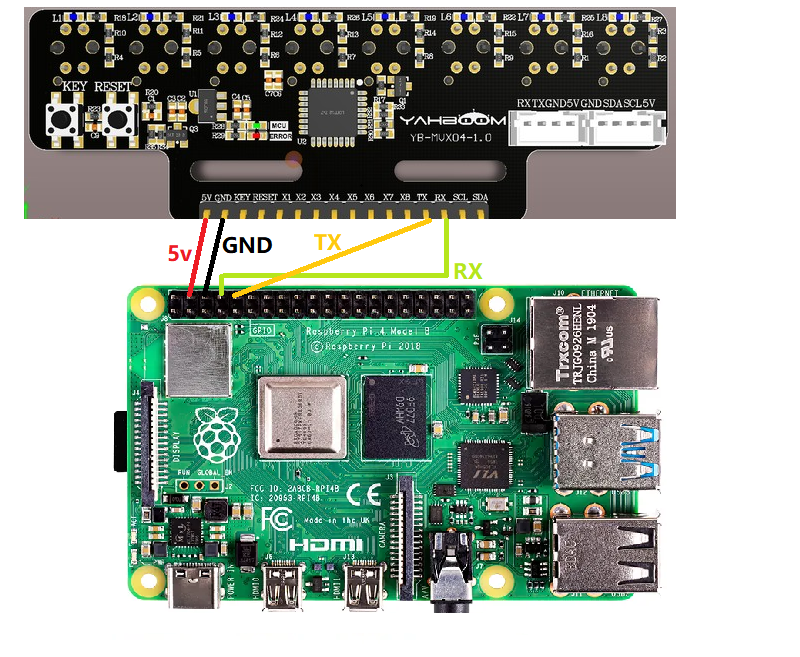
Experimental wiring
| Raspberry Pi | 8-channel line patrol module |
|---|---|
| TX | RX |
| RX | TX |
| 5v | 5v |
| GND | GND |
As shown in the figure:
Open the Raspberry Pi hard serial port (Raspberry Pi 5 does not require this step)
Configure the Raspberry Pi serial port first, because the Raspberry Pi's hard serial port is used for Bluetooth, and the mini serial port is unstable. This experiment uses the hard serial port. Raspberry Pi pin diagram
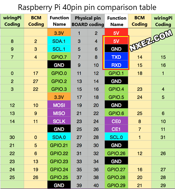
First perform the following operations to map the serial port Enter
sudo raspi-configin the terminal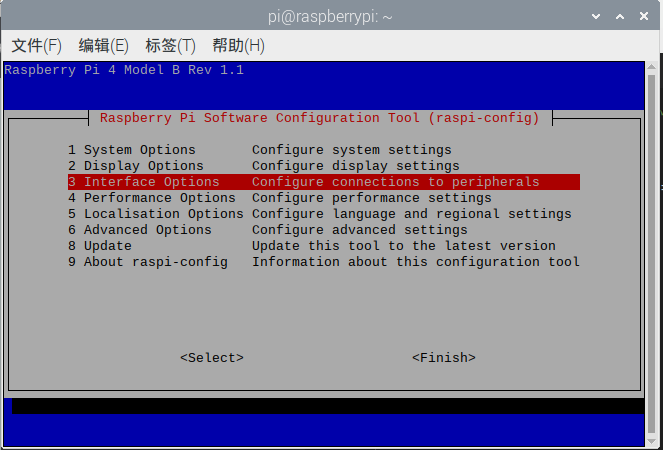
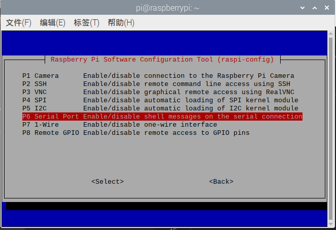
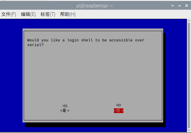
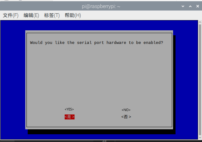
Set the hardware serial port to GPIO serial port, edit /boot/config.txt with root privileges.
The command is:
sudo nano /boot/config.txtAfter opening the file, add two lines at the end
xxxxxxxxxxdtoverlay=miniuart-btforce_turbo=1
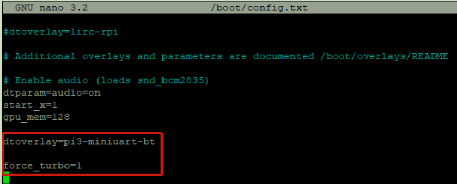 Save: Ctrl+O, exit: Ctrl+X.
Save and exit, then restart the Raspberry Pi and you can see that the serial ports have been swapped.
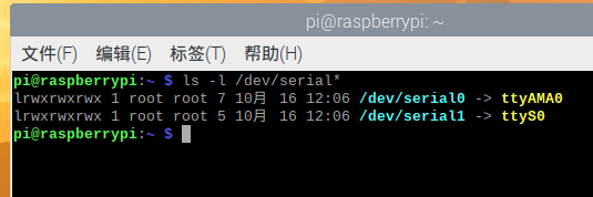 Reference Links: https://blog.iyatt.com/?p=1817
Experimental steps and phenomena
After connecting the wires, run the script
xxxxxxxxxxpython3 UASRT.py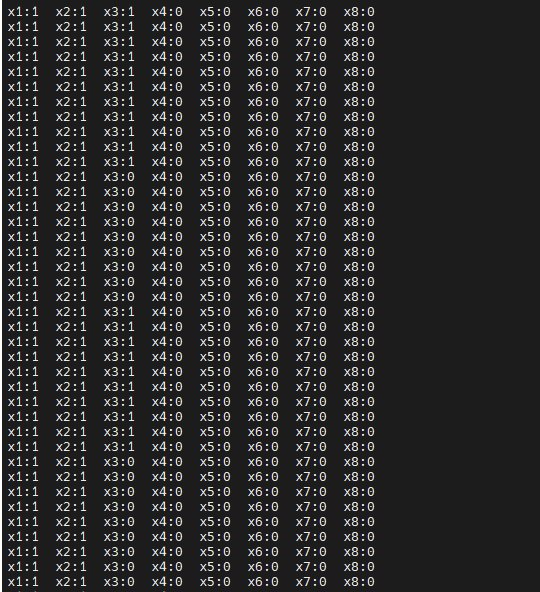
Experimental source code
xxxxxxxxxx#Main functionif __name__ == "__main__": print("start it") try: while True: usart_deal() except KeyboardInterrupt: pass finally: ser.write(bytes("$0,0,0#",'utf-8'))This source code only writes numerical data. If you need to parse analog data, you can refer to STM32 serial port parsing