Welcome to 8-Channel Tracking Module repository
I2C method
MSPM0-IO Method
MSPM0-IO MethodExperimental preparationExperimental purposeExperimental wiringExperimental steps and phenomenaExperimental source code
Experimental preparation
TI's MSPM0G3507 motherboard
8-channel patrol module
Several Dupont cables
MSPM0G3507 board needs to download the I2C communication source code provided in the document**
Experimental purpose
The content of this experiment is mainly to use the MSPM0G3507 master control to receive the data of the 8-channel patrol module through I2C.
Experimental wiring
MSPM0G3507 connected to the serial port assistant If the type-c port of the msp does not have the function of downloading programs, you need to use a USB to TTL module to connect to the computer. The wiring is described in the following table
| MSPM0G3507 | usb to ttl |
|---|---|
| PA10 | TX |
| PA11 | RX |
| vcc | vcc |
| GND | GND |
| If the MSPM0G3507 MCU type has a download function, you can directly use the type-c to connect to the computer's serial port assistant |
| MSPM0G3507 | 8-channel line patrol module |
|---|---|
| PA0 | SDA |
| PA1 | SCL |
| 5v | 5v |
| GND | GND |
Experimental steps and phenomena
After connecting the wires, open the serial port assistant and you can see the numerical data of the infrared module. Set the baud rate to 115200. As shown in the figure below
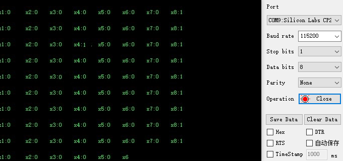
MSPM0 developers need to build the environment before compiling and running the project Environment building tutorial: https://wiki.lckfb.com/zh-hans/dmx/beginner/install.html
Experimental source code
x//Main functionint main(void){ SYSCFG_DL_init(); //Wait for the infrared module to be normal delay_ms(1000); delay_ms(1000);
//Clear the serial port interrupt flag NVIC_ClearPendingIRQ(MYUART_INST_INT_IRQN); //Enable serial port interrupt NVIC_EnableIRQ(MYUART_INST_INT_IRQN);
printf("start\r\n"); IRI2C_WriteByte(0x01,1);//Control access calibration delay_ms(200); IRI2C_WriteByte(0x01,0);//Control exit calibration delay_ms(200); printf("okok\r\n"); while (1) { printf_i2c_data(); delay_ms(500); }}
Before powering on, press and hold the reset pin of mspM0, wait for the infrared module to work normally, and then release the reset button of MSP, otherwise it is easy to cause i2c deadlock. The main function of the source code is very simple, reading the probe pins of 8-way patrol line and printing them out.