Welcome to 8-Channel Tracking Module repository
Serial Port method
MSPM0-UASRT Method
MSPM0-UASRT MethodExperimental preparationExperimental purposeExperimental wiringExperimental steps and phenomenaExperimental source code
Experimental preparation
TI's MSPM0G3507 motherboard
8-channel patrol module
Several Dupont cables
MSPM0G3507 board needs to download the UASRT communication source code provided in the document**
Experimental purpose
The content of this experiment is mainly to use the MSPM0G3507 master control to receive the data of the 8-channel patrol module through UASRT.
Experimental wiring
MSPM0G3507 connected to the serial port assistant If the type-c port of the msp does not have the function of downloading programs, you need to use a USB to TTL module to connect to the computer. The wiring is described in the following table
| MSPM0G3507 | usb to ttl |
|---|---|
| PA10 | TX |
| PA11 | RX |
| vcc | vcc |
| GND | GND |
| If the MSPM0G3507 MCU type has a download function, you can directly use the type-c to connect to the computer's serial port assistant |
| MSPM0G3507 | 8-channel line patrol module |
|---|---|
| PA9 | TX |
| PA8 | RX |
| 5v | 5v |
| GND | GND |
Experimental steps and phenomena
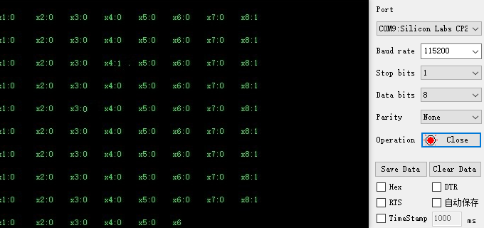
After connecting the wires, open the serial port assistant and you can see the numerical data of the infrared module. Set the baud rate to 115200. As shown in the figure below
MSPM0 developers need to build the environment before compiling and running the project Environment building tutorial: https://wiki.lckfb.com/zh-hans/dmx/beginner/install.html
Experimental source code
x
int main(void){ //Development board initialization board_init(); delay_ms(500); delay_ms(500); uart1_send_string("$0,0,1#"); IR_usart_config(); // Serial port initialization printf("start\r\n"); while(1) { //Parsing the data sent IRDataAnalysis(); delay_ms(500);
}}uart1_send_string("$0,0,1#");:The first number is the calibration mode (0: exit calibration mode 1: enter calibration mode) The second number is whether to receive analog data The third number is whether to receive numerical data. This routine only provides parsing of numerical data. If you need to parse analog data, you can parse it yourself according to the protocol. The serial port parsing file of this project also has a function for parsing analog values. You can refer to the Deal_Usart_AData function.