Welcome to 8-Channel Tracking Module repository
1.STM32-Wheeled car chassis_V1
STM32mini chassis car line patrol
STM32mini chassis car line patrol1. Experimental Preparation2. Trolley wiring2.1 STM32 and dual-channel driver board wiring part2.2 Wiring of STM32RCT6 and infrared sensor (this example uses serial communication)Main proceduresExperimental phenomenon:
1. Experimental Preparation
Knowledge reserve
Have good programming skills (mainly C language)
Familiar with the architecture of stm32
Material preparation
Smart car mini chassis *1
stm32F103RCT6 *1 (requires the board of the Yabo board, other boards need to change the source code)
Yabo version of the dual-channel motor driver board *2 (other motor driver boards may not be suitable for the source code provided in this tutorial, need to be transplanted by yourself)
Eight-way tracking module *1
310 motor *4
7.4V battery *1
Several Dupont wires
Several M3 copper pillars and M3 screws
2. Trolley wiring
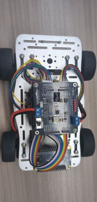
After assembling the car, it looks like the following figure:
2.1 STM32 and dual-channel driver board wiring part
Wiring of stm32F103RCT6 and dual-circuit motor board (topmost board)
| STM32RCT6 | The top dual-circuit motor board |
|---|---|
| PA11 | AIN1 |
| PA8 | AIN2 |
| PC6 | BIN1 |
| PC7 | BIN2 |
| 3V3 | 3V3 |
| GND | GND |
| PA0 | E1A |
| PA1 | E1B |
| PA15 | E2A |
| PB3 | E2B |
| 5V | 5V |
Wiring of stm32F103RCT6 and dual-circuit motor board (bottommost board)
| STM32RCT6 | The bottom layer dual-circuit motor board |
|---|---|
| PB0 | AIN1 |
| PB1 | AIN2 |
| PC8 | BIN1 |
| PC9 | BIN2 |
| 3V3 | 3V3 |
| GND | GND |
| PA7 | E1A |
| PA6 | E1B |
| PB7 | E2A |
| PB6 | E2B |
The top motor driver board is connected to the motors of the two wheels near the infrared sensor (the front motors),
motorA--->left motor, motorB--->right motor
The bottom motor driver board is connected to the motors of the two wheels away from the infrared sensor (the rear motors),
motorA--->left motor, motorB--->right motor
2.2 Wiring of STM32RCT6 and infrared sensor (this example uses serial communication)
| STM32RCT6 | Infrared sensor |
|---|---|
| PC10 | RX |
| PC11 | TX |
| No wiring | VCC is connected to the 5V interface of the top dual-circuit motor board |
| GND | GND |
Main procedures
xint main(void){ //Hardware Initialization BSP_init(); while(!Key1_State(1));//Waiting for a key press TIM6_Init();//Timer 6 initialization send_control_data(0,0,1); //Set to receive only numeric data while(1) { LineWalking(); //Faster response }}
The main function is to perform PID processing for line patrol according to the value of the infrared probe, so that line patrol can be completed on the map with black lines and white background.
In app_irtrackin.c, there is a parameter for adjusting PID line patrol. If you want to increase or decrease the speed and optimize the effect, you can adjust the macro definition value inside.
xxxxxxxxxx
//P//I//D
//Line patrol speedIRTrack_Trun_KP: P value of pid line patrol
IRTrack_Trun_KI: I value of pid line patrol
IRTrack_Trun_KD: D value of pid line patrol
IRR_SPEED: Speed of line patrol
When you want to check whether the motor wiring is correct, you can give a positive speed and then set the line patrol PID value to 0. If the wiring is correct, after pressing the key button on the RCT6 development board, the car will move forward and all four motors will move forward.
Experimental phenomenon:
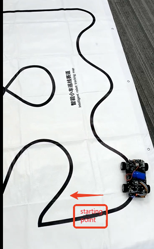
On the premise of ensuring that the wiring and installation are correct, after the 8-way patrol module is calibrated, (if the same map as the tutorial is used), you need to put the car under the starting point diagram as shown below, and press the key1 button to start patrolling.
If the 8-way module probe cannot detect the black and white lines normally, you need to wait for the module to work normally before pressing the key1 button
If the floor is black, you need to put a piece of white paper under our map to cover the black. The main reason is that the material of the map is relatively transparent, which has a greater impact on the 8-way patrol sensor.