Welcome to WiFi Camera Module repository
4. Raspberry Pi
Raspberry Pi configuration camera
Raspberry Pi configuration camera1. Experiment preparation2. Experimental wiring3. Open the Raspberry Pi hard serial port (this step is not required for Raspberry Pi 5)4. Experimental steps and experimental results5. Analysis of wifi configuration source code
1. Experiment preparation
- raspberry pie
- wifi camera
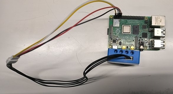
2. Experimental wiring
as the picture shows

3. Open the Raspberry Pi hard serial port (this step is not required for Raspberry Pi 5)
- Configure the Raspberry Pi serial port first, because the hard serial port of the Raspberry Pi is used for Bluetooth, and the mini serial port is unstable to use. This experiment uses the hard serial port.
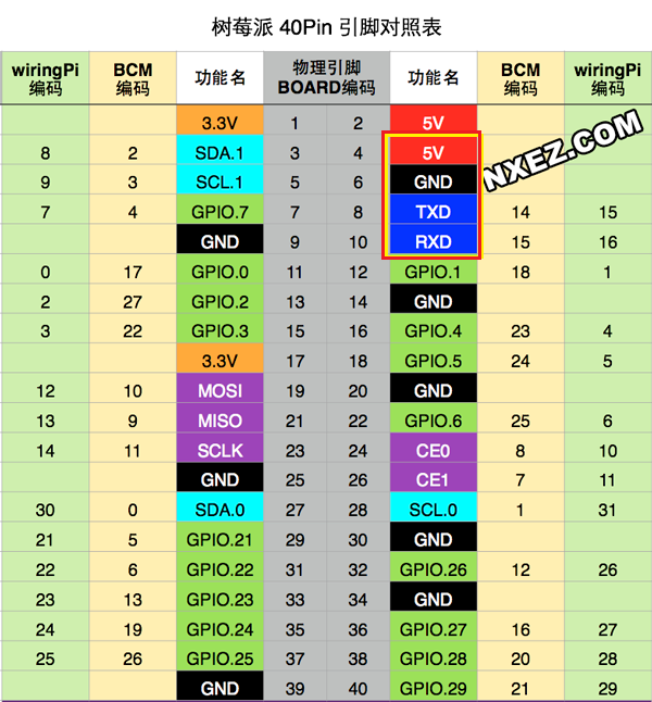
Raspberry Pi pin diagram
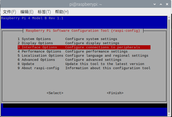
- First perform the following operations to map the serial port Enter sudo raspi-config in the terminal
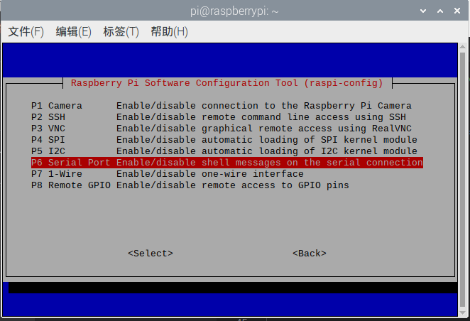
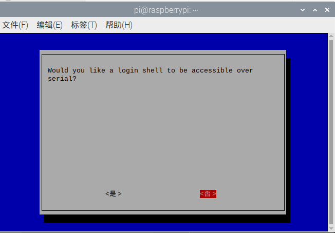
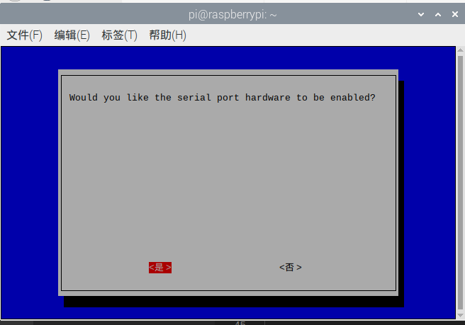
- Set the hardware serial port to GPIO serial port and edit /boot/config.txt with root permissions That is, the command is:
xxxxxxxxxxsudo nano /boot/config.txtAfter opening the file, add two lines at the end
dtoverlay=miniuart-bt
force_turbo=1
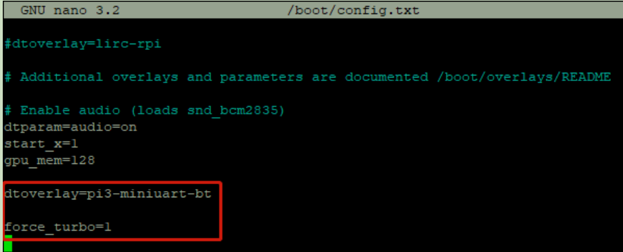 Save: Ctrl+O, exit Ctrl+X.
- After saving and exiting, restart the Raspberry Pi. You can see that the serial ports have been swapped.
 Reference link: https://blog.iyatt.com/?p=1817
4. Experimental steps and experimental results
- Open a new Raspberry Pi terminal and send the source code of this experiment to the Raspberry Pi.
- Execute the following instructions
xxxxxxxxxxpython3 PI_SET_WIFI.py- If it is opened successfully, the following results will appear
 This information is related to configuring the camera wifi mode, reading version information and other related operations.
 - If the AP+STA mode is turned on, then the IP addresses of the AP+STA will have the correct IP address (this source code is in this mode)
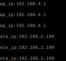 If only one mode is enabled, then sta_ip:null or ap_ip:null
When sta_ip:null occurs, you need to check whether the connected wifi name and password are correct. If correct, whether only the AP mode is turned on and the STA mode is not turned on.
If only one mode is enabled, then sta_ip:null or ap_ip:null
When sta_ip:null occurs, you need to check whether the connected wifi name and password are correct. If correct, whether only the AP mode is turned on and the STA mode is not turned on. - Transparent data transmission based on IP connection
First open the NetAssist.exe software on your computer and make sure the computer and camera are on the same network segment.
Then connect according to the obtained IP address. For example, the obtained sta_ip is: "192.168.2.199"/ap_ip is: "192.168.4.1"
Then there are 2 ways
- Connect the computer to the camera's spontaneous wifi, and then connect through the ip 192.168.4.1. The port number is 8888 and cannot be changed.
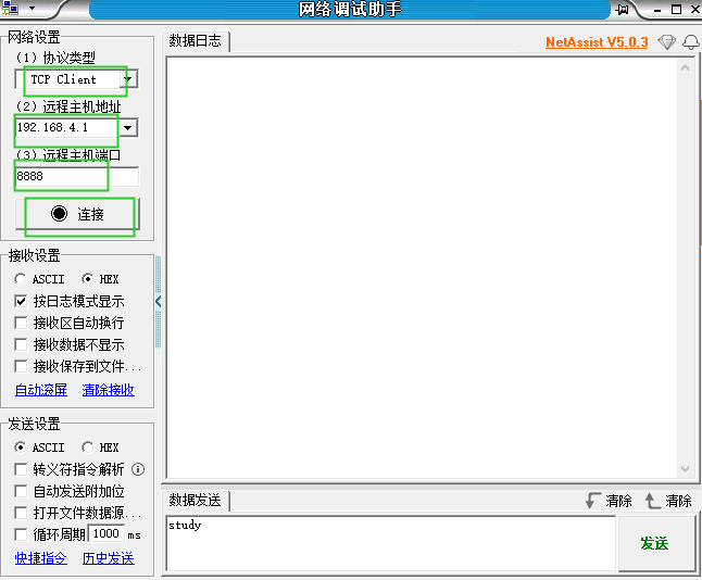
- The computer is connected directly through the IP address 192.168.2.199. The port number is 8888 and cannot be changed. The following figure is a diagram of a successful connection.
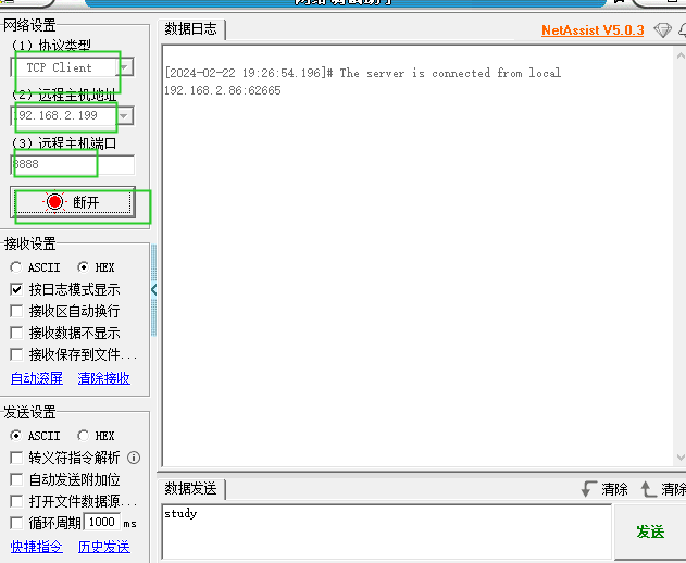
- Connect the computer to the camera's spontaneous wifi, and then connect through the ip 192.168.4.1. The port number is 8888 and cannot be changed.
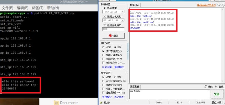
Then by sending the information, the Raspberry Pi terminal will also print the relevant information
- View camera footage
Open the browser on your computer or mobile phone
Then watch the video through the obtained IP address. For example, the obtained sta_ip is: "192.168.2.199"/ap_ip is: "192.168.4.1"
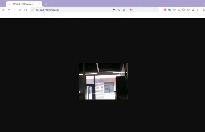
Then you can watch the live camera footage in 2 ways
- Connect the computer to the camera's spontaneous wifi, and then enter http://192.168.4.1:81/stream through the browser to access the camera screen
- Directly enter http://192.168.2.199:81/stream on your computer to access the camera screen.
5. Analysis of wifi configuration source code
xxxxxxxxxxSta_wifi_ssid = "Yahboom"Sta_wifi_pd = "yahboom"AP_wifi_ssid = "ESP_WIFI_TEST"AP_wifi_pd = ""wifi_mode = '2'- Sta_wifi_ssid: The wifi name of sta is the name of the wifi to be connected
- Sta_wifi_pd: sta's wifi is the password of the wifi to be connected
- AP_wifi_ssid: The name of the wifi camera's spontaneous hotspot
- AP_wifi_pd: Password for wifi camera spontaneous hotspot
- wifi_mode: Working mode of wifi camera '0': AP mode '1': STA mode '2': AP+STA mode