Welcome to WiFi Camera Module repository
pico car
PicoRobot and camera
PicoRobot and camera1. Experiment preparation2. Experimental wiring3. Experimental steps and experimental results4. Main source code analysis
1. Experiment preparation
- One pico car
- Several male-to-male Dupont lines
- esp32-wifi camera
- The serial port cable that comes with the camera
2. Experimental wiring
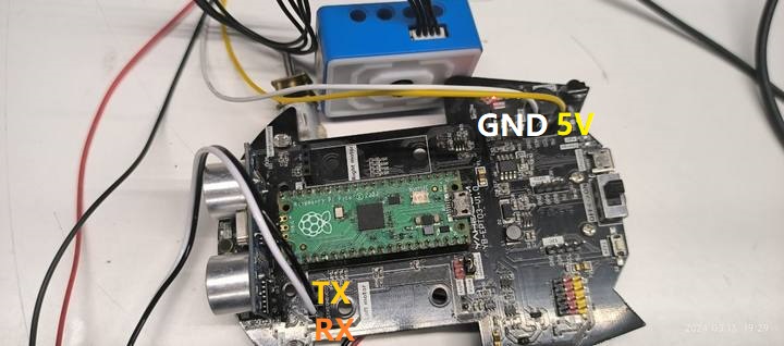
Fix the camera behind the car, connect it to the Bluetooth interface of the pico car, and arrange the interface cable
| Camera | pico car |
|---|---|
| RX | RX |
| TX | TX |
| VCC | VCC |
| GND | GND |
as the picture shows
3. Experimental steps and experimental results
Burn the program of this experiment into the car. For how to download the program and burn the related firmware, please refer to the chapters of PICO Robot for downloading the program and burning the firmware. This experiment will not explain it again.
After confirming that the wiring is correct, turn on the car battery switch, install the ESP32Cam software on your phone, open it, and log in directly.
Connect the mobile phone to the camera's spontaneous wifi. The wifi name of this routine is ESP32_WIFI_TEST, and you can connect directly without a password. Note: If you have changed the wifi name and password of the program, find and connect by yourself
After the connection is successful, keep the connection and do not disconnect. Enter the mobile app settings page and set the IP address to 192.168.4.1
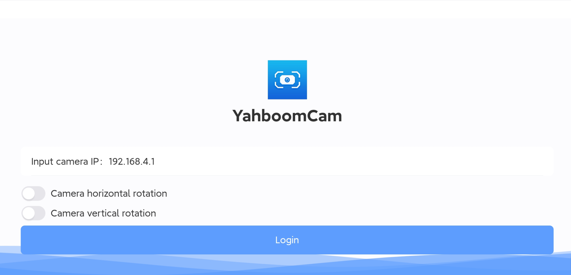
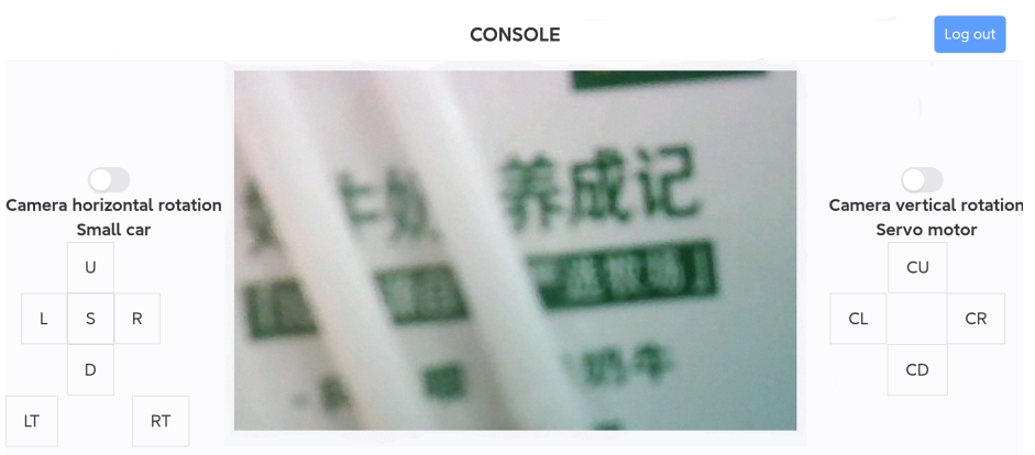
Then click on the login page to successfully see the camera image and control the movement of the car. Horizontal screen
4. Main source code analysis
The above constants are defined in the esp32_wifi.c source code of this project
- AP_WIFI_SSID: The wifi name of the wifi camera's spontaneous hotspot, change it according to your own situation
- AP_WIFI_PD: The wifi password of the wifi camera's spontaneous hotspot, change it according to your own situation
If you want to change the wifi mode, this tutorial defaults to dual mode coexistence, that is, STA+AP mode Select the mode under the file esp32_wifi.h
xxxxxxxxxx#define MODE_AP 0#define MODE_STA 0#define MODE_AP_STA 1
0: represents canceling this mode 1: represents selecting this mode You can only choose one mode, not at the same time, otherwise the IP address will not be queried