Welcome to WiFi Camera Module repository
7. Implementation of visual line inspection solution
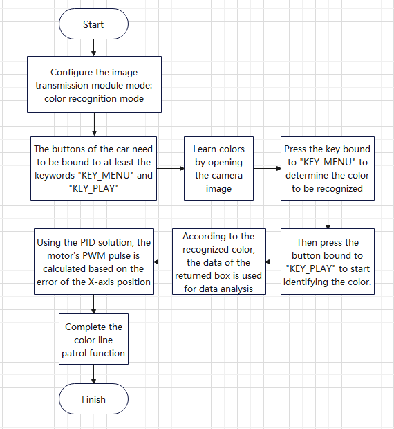
Implementation of visual line patrol solution
It is recommended that those with zero basics first improve their knowledge of microcontrollers, car control, pid, etc., and then read this tutorial
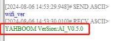
- First determine whether the version of the image transmission module is the AI version firmware. If you already know the firmware version, you can ignore this step and use the wifi_ver command to query, as shown in the figure below
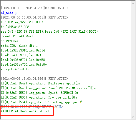
- Switch the mode to color recognition mode and send the following command through the serial port assistant ai_mode:3, after successful configuration, the module will restart and print the current firmware version, and then color recognition can begin, as shown in the figure
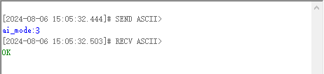
Note: If the current mode is already in color recognition mode, the module only returns ok
The first two steps can be sent directly using the microcontroller master control. You can refer to the Master control configuration wifi camera section. The serial port baud rate of the master control is: 115200, 8 data bits, 1 stop bit.
- From this step, you need to keep the photos of the image transmission module open normally. You can use the app to browse the page or use the browser to access it. The IP address to access is 192.168.4.1. Connect to the hotspot generated by the image transmission module.
- To start recording the color, you need to define the buttons of the car. Each time you press the button, use the serial port to send the keyword KEY_MENU to the image transmission module. After the image transmission module receives it, an admission box will appear on the screen, as shown in the figure
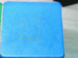 Warm Tips: You can send KEY_UPUP** through the serial port to increase the selection of the admission box, and send KEY_DOWN to reduce the selection of the box**. These keywords can be realized by using the buttons of the car
KEY_UPUP:
Warm Tips: You can send KEY_UPUP** through the serial port to increase the selection of the admission box, and send KEY_DOWN to reduce the selection of the box**. These keywords can be realized by using the buttons of the car
KEY_UPUP:
KEY_DOWN:
- After selecting the color, define the car's buttons and send KEY_PLAY through the serial port. After confirming the selected color, the screen's entry box will disappear, and then the color just entered will be directly recognized. And send the coordinates of the upper left corner and lower right corner of the first recognized box through the serial port. The specific content is $upper left corner x-axis coordinate, upper left corner y-axis coordinate, lower right corner x-axis coordinate, lower right corner y-axis coordinate, # Note: You need to open the screen to start recognition. If the screen is closed in the middle, the recognition will also be closed.
Result:
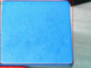
Serial port information:
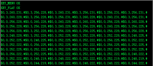
- Calculate the position of the identification frame according to the protocol The calculation is as follows: the upper left corner x-axis coordinate + (lower right corner x-axis coordinate - upper left corner x-axis coordinate)/2 is the position of the center point of the frame. For line patrol, you only need to calculate the direction of the X axis, and the Y axis direction only needs to give a forward speed. For example: the x-axis coordinate of the lower right corner is 180, and the x-axis coordinate of the upper left corner is 90, then the coordinate of the center point is 90+(180-90)/2 = 135 However, the size of the entire image is 320*240 resolution, so the absolute center of the x-axis is 160.
- Using the error of the x-axis, calculate the pwm error to be corrected through the position-based pid. The formula of pid is as follows, and the output value is the pwm pulse of the corrected motor
Out=pid.Kppid.err+pid.Kipid.integral (accumulated error)+pid.Kd*(pid.err-pid.err_last);
The pulse output by pid plus the speed pwm pulse of the motor in the Y-axis direction is the total pwm pulse output by a single motor.
- Finally, adjust the parameters of pid to patrol the track according to your own color.
The following is a detailed flowchart of the solution