Welcome to WiFi Camera Module repository
3. STM32 car (with PTZ)
stm32 development board car and camera
stm32 development board car and camera1. Experiment preparation2. Wiring diagram3. Experimental steps and experimental resultsIntroduction to the main program source code of wifi configuration
1. Experiment preparation
- STM32 development board car
- wifi camera
2. Wiring diagram
| STM32F103 | wifi camera |
|---|---|
| PD5 | RX |
| PD6 | TX |
| GND | GND |
| 5V | 5V |
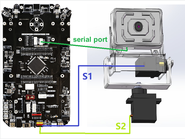
as the picture shows:
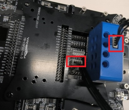
Wiring of servo gimbal
- Connect the servo of the up and down direction of the servo gimbal to the S1 interface of the servo interface on the car board
- Connect the left and right servos of the servo gimbal to the S2 interface of the servo interface on the car board
3. Experimental steps and experimental results
Shortcut method: You can directly connect to the wifi opened by esp32. In this experiment, the name is ESP32_WIFI_TEST, and then the ip address camera information of the mobile app is 192.169.4.1 to control the car
- Check whether the program is running normally
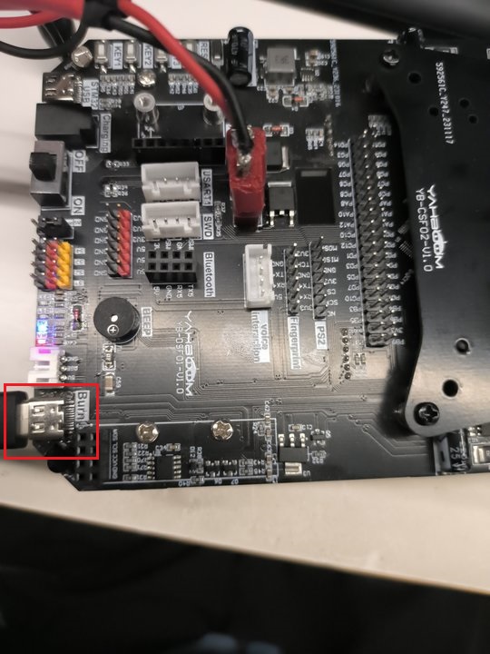
- After downloading the program of this project to the stm32 car, plug in the serial port, as shown in the figure below
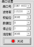
- Open the serial port assistant on the computer, open the computer and detect the stm32 serial port, as shown below
- After pressing the reset button of stm32, the serial port assistant will print out the corresponding information.
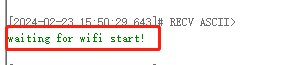
- Wait for about 30 seconds and the corresponding wifi information will be printed.
If the AP+STA mode is turned on, then the IP addresses of the AP+STA will have the correct IP address (this source code is in this mode)
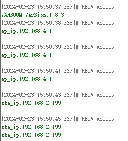
If only one mode is enabled, then sta_ip:null or ap_ip:null When sta_ip:null occurs, you need to check whether the connected wifi name and password are correct. If correct, whether only one mode of AP is turned on and the STA mode is not turned on.
- Use the app to control the movement of the car. After installing the "ESP32Cam" app, open it.
On the login page, set according to the IP obtained by the serial port assistant. For example, the IP obtained by the serial port assistant is "192.168.2.199", then the configuration is as follows
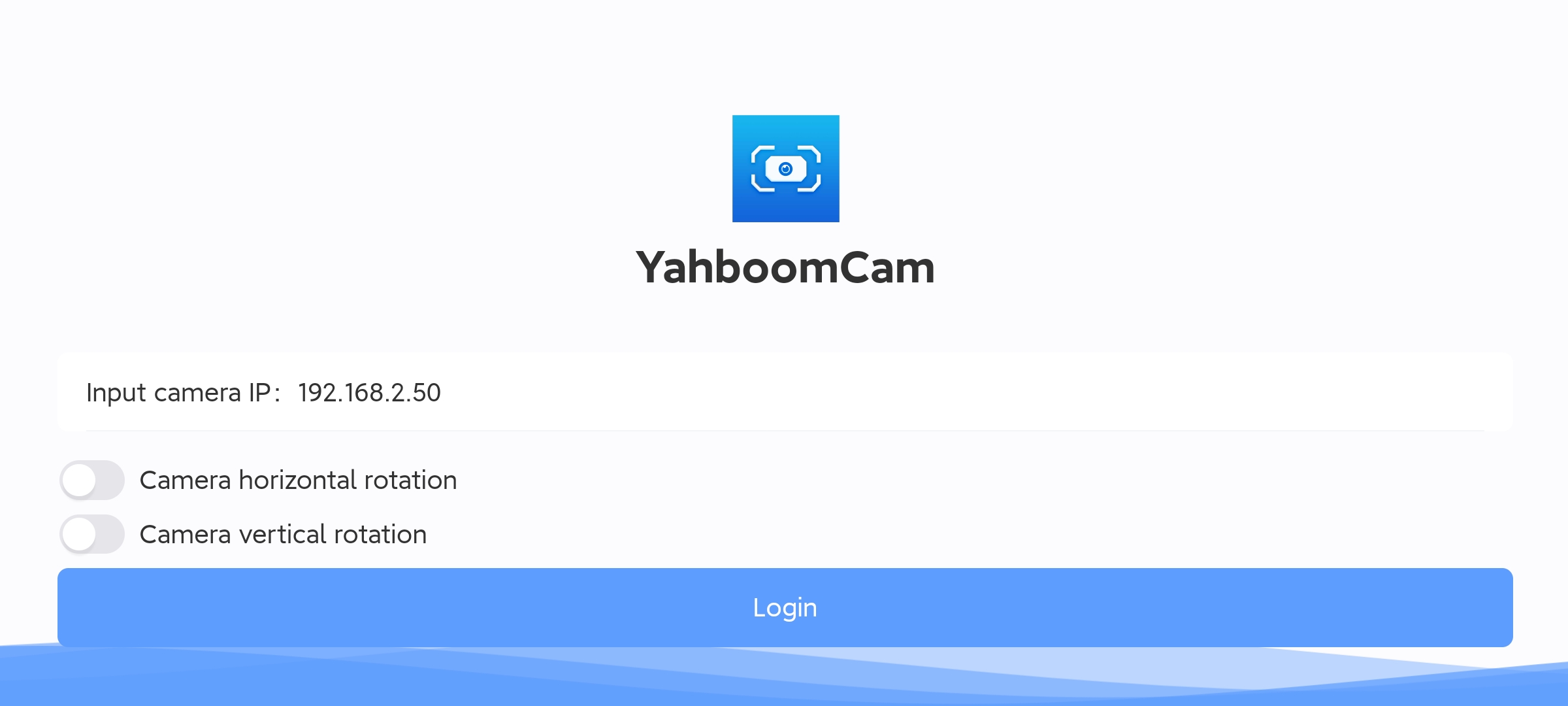
Then click to log in directly
(Optional) If you want to connect to the hotspot of the wifi camera, the IP address must be set to 192.168.4.1, as shown in the picture
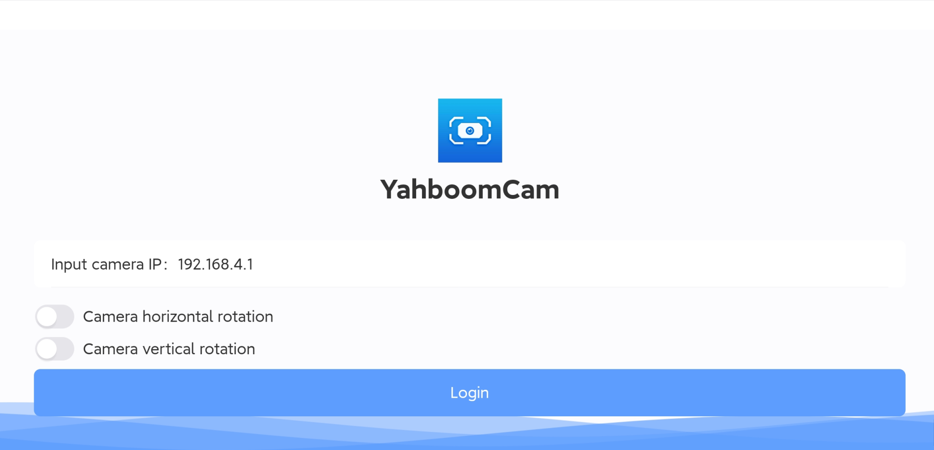
- When the IP address is configured correctly and successfully connected, you can control the car through the app console page.
Horizontal screen
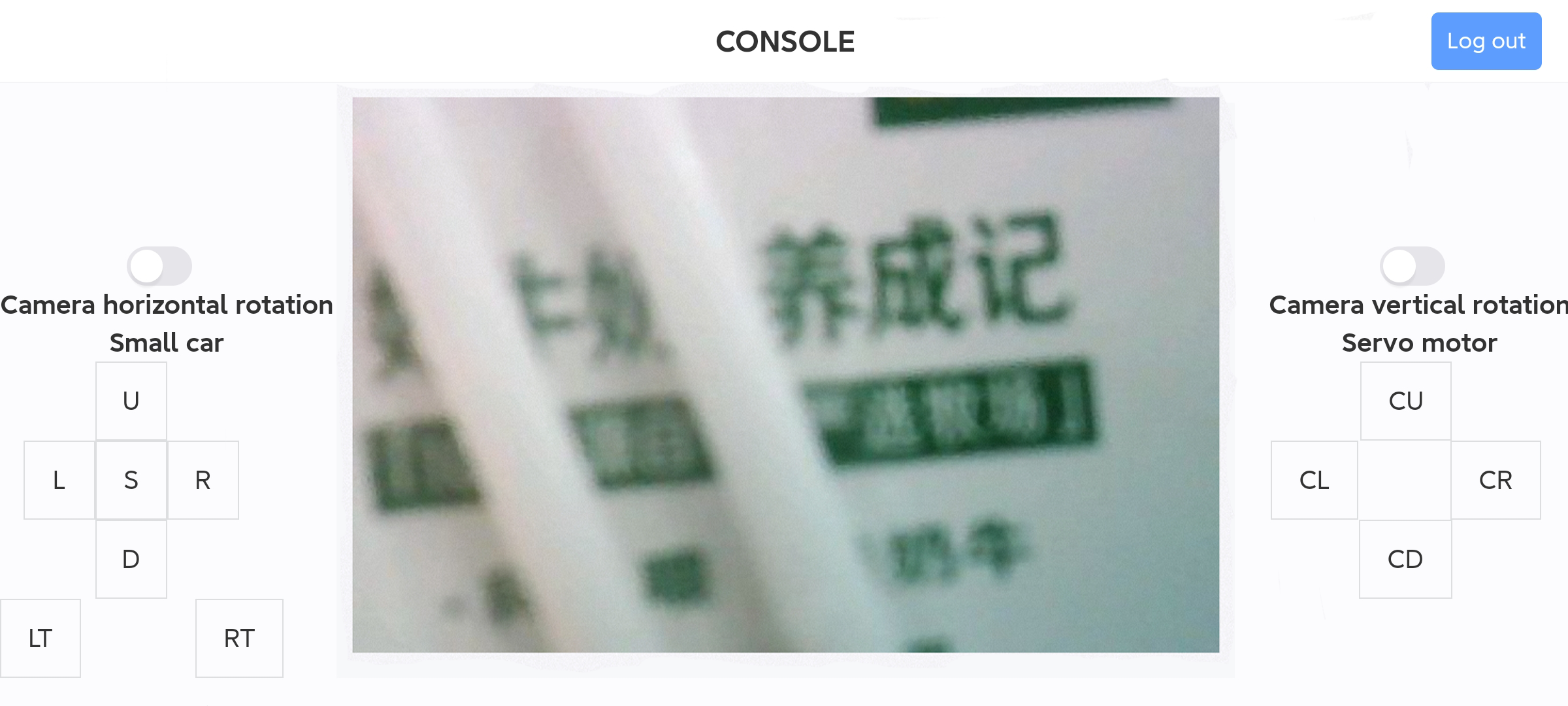
xxxxxxxxxxNote: Every time you restart the app, you need to click the exit button in the upper right corner, then exit and reconfigure the IP address information before logging in.
Introduction to the main program source code of wifi configuration
xxxxxxxxxxThe above constants are defined in the esp32_wifi.c (standard library)/bsp_wifi.c (HAL library) source code of this project
- STA_WIFI_SSID: The name of the wifi to be connected, change it according to your own situation
- STA_WIFI_PD: The wifi password to be connected, change it according to your own situation
- AP_WIFI_SSID: The wifi name of the wifi camera's spontaneous hotspot, change it according to your own situation
- AP_WIFI_PD: The wifi password of the wifi camera's spontaneous hotspot, change it according to your own situation
If you want to change the wifi mode, this tutorial defaults to dual mode coexistence, that is, STA+AP mode Select the mode under the file esp32_wifi.h
xxxxxxxxxx#define MODE_AP 0#define MODE_STA 0#define MODE_AP_STA 1
0: represents canceling this mode 1: represents selecting this mode You can only choose one mode, not at the same time, otherwise the IP address will not be queried