Welcome to 10-axis IMU Navigation Module repository
ROS2 application case tutorial
Environment build
This course explains how to build a ten-axis IMU module environment in ros2, including compiling function packages, binding serial ports, running programs and viewing data. This section takes ubuntu20.04+ros-foxy, the function package space name is WitImu_ws as an example, and the default baud rate is 9600.
1、Compile feature pack
Create a workspace WitImu_ws and create a new src folder in this directory to store the function package. Terminal input,
mkdir WitImu_wscd WitImu_wsmkdir srcThen unzip the file to get the wit_ros2_imu folder, copy it to the src directory just created. Next go back to the workspace directory, use the colcon build command to compile, and enter in the terminal,
xxxxxxxxxxcd ~/WitImu_wscolcon buildFinally, add the path of the workspace to .bashrc. Terminal input,
xxxxxxxxxxsudo vim ~/.bashrcsource ~/WitImu_ws/install/setup.bash #Add this sentence at the end, here my workspace is in the ~ directory, modify it according to your own workspace directory2、Bind serial port
In order to prevent the system from identifying errors when multiple usb devices are plugged in at the same time, we bind the serial port name of the module to /dev/imu_usb. Enter the terminal,
xxxxxxxxxxcd ~/WitImu_ws/src/wit_ros_imusudo chmod 777 bind_usb.shsudo sh bind_usb.shPlug and unplug the USB data cable connected to the IMU module again. To effectively bind the port, enter the following command to check whether the binding port is successful,
xxxxxxxxxxll /dev/imu_usb
Note: It does not have to be ttyUSB0, as long as it is displayed as a USB device.
3、run test
Terminal input,
xxxxxxxxxxros2 launch wit_ros2_imu rviz_and_imu.launch.py 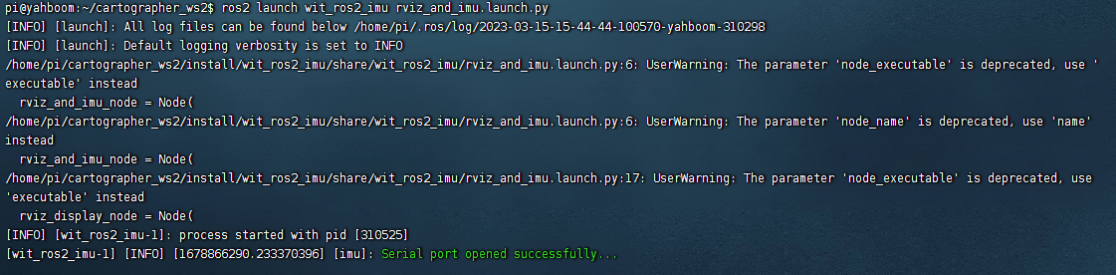
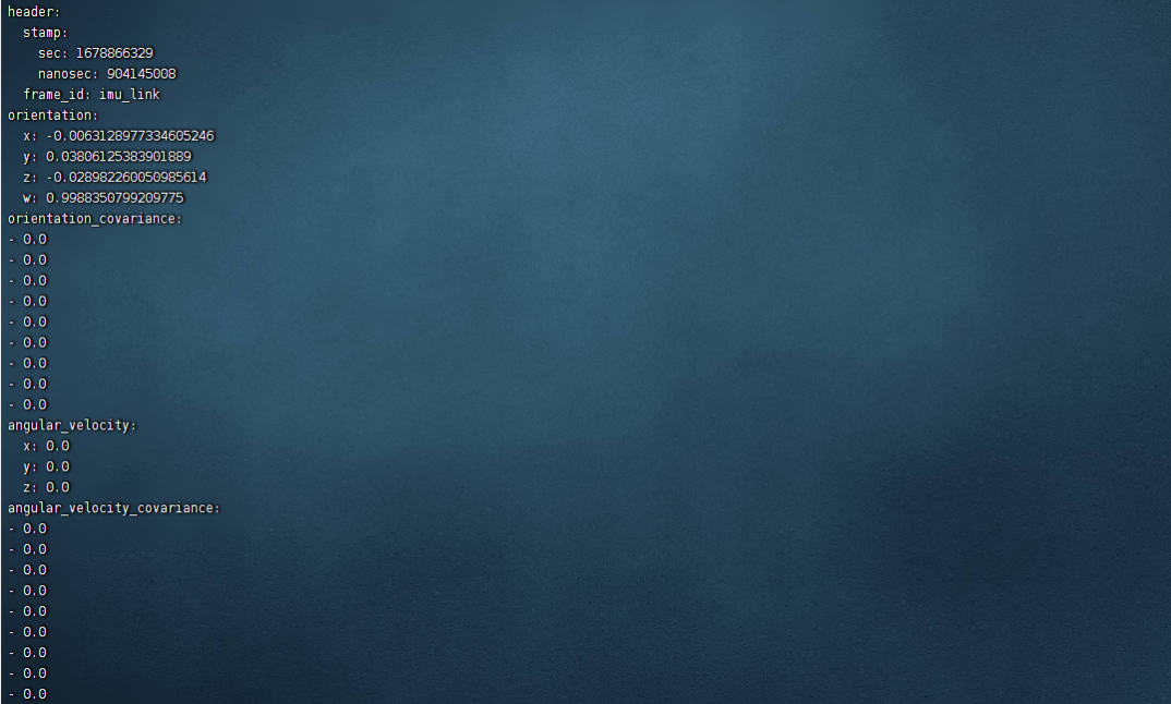
Use the “ros2 topic echo” tool to see the specific content of the published data. Terminal input,
xxxxxxxxxxros2 topic echo /imu/data
4、Modify the baud rate
By default, the program uses a baud rate of 9600. If the baud rate is modified on the host computer, then the baud rate in the source code needs to be modified. The location of the source code to modify the baud rate is ~/WitImu_ws/src/wit_ros2_imu/wit_ros2_imu/ wit_ros2_imu.py
xxxxxxxxxx#line 149def driver_loop(self, port_name):# open serial port try: wt_imu = serial.Serial(port="/dev/imu_usb", baudrate=9600, timeout=0.5)Change 9600 to the baud rate modified on the host computer, then save and exit, and finally return to the workspace directory to compile.