Welcome to MSPM0G3507 Development Board repository
6. Timer
Timer
Timer1. Learning ObjectivesTimerBasic parameters of the timer2. Hardware construction3. Experimental steps1. Open the SYSCONFIG configuration tool2. Timer parameter configuration3. Write the program4. Compile4. Program Analysis5. Experimental phenomenon
1. Learning Objectives
- Learn the basic use of the MSPM0G3507 motherboard timer.
- Realize the timed flipping of LED status.
Timer
The timer is a very important peripheral in the microcontroller, used for timing and generating timed interrupts. The core principle of the timer is to record time through an internal counter. The counter is incremented by one per machine cycle. When the counter reaches a preset value, it triggers an interrupt. The program can perform certain operations in the interrupt service program, such as flipping LEDs, reading sensor data, controlling motors, etc.
Basic parameters of the timer
- Prescaler
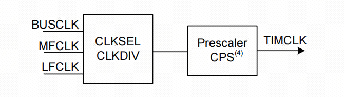
The prescaler can divide the timer clock (TIMCLK) frequency by any value between 1 and 256 (1 to 256 is based on the 8-bit timer divider). TIMG can choose BUSCLK, MFCLK, LFCLK as the clock source, and can divide the clock by a maximum of 8. After passing through an 8-bit prescaler, it is finally called the timer count clock.
- Up or down counting mode
Up counting means that the counter starts counting from 0 to the auto-load value. Once the counter counts to the auto-load value, it will start counting from 0 again and generate an overflow event. Down counting means that the counter starts counting from the auto-load value to 0. Once the counter counts to 0, it will start counting from the auto-load value again and generate an underflow event.
- Update event
The update event is triggered when the counter overflows or underflows and starts a new counting cycle. The update event can trigger a DMA request to update the timer's operating parameters in time at the beginning of the next counting cycle, which is particularly suitable for real-time control.
2. Hardware construction
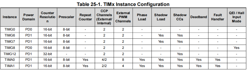
The MSPM0G series has a total of 7 timers, which can be divided into 2 types, general timers (TIMG) and advanced control timers (TIMA). Different types of timers have different numbers of functions. Generally, advanced timers have the most functions, followed by general timers.
3. Experimental steps
If the project needs to execute or repeat specific tasks at a fixed time, the configuration of the timer is particularly important. The following will introduce how to set the timer to trigger an interrupt every 1 second, and implement the LED state flip in the interrupt service function, so as to achieve the effect of LED on for 1 second and off for 1 second.
1. Open the SYSCONFIG configuration tool
Open the blank project empty in the SDK in KEIL.
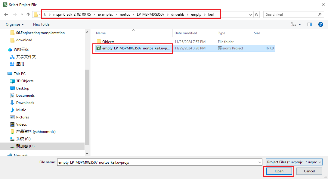
Select and open, open the empty.syscfg file in the keil interface, with the empty.syscfg file open, then select to open the SYSCONFIG GUI interface in the Tools column.
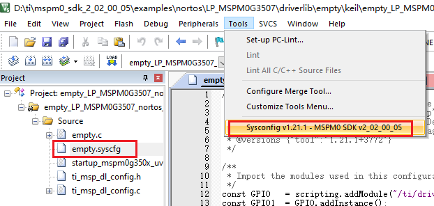
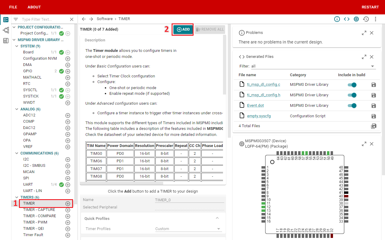
In SYSCONFIG, select MCU peripherals on the left, find the TIMER option and click to enter. Click ADD in TIMER to add a timer peripheral.
2. Timer parameter configuration
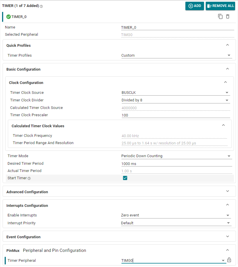
In this case, select BUSCLK-32MHz for the Timer Clock Source, select 8 for the Timer Clock Divider, and configure 100 for the Timer Clock Prescaler, so the timer frequency is 40KHz. Desired Timer Period sets the timer period to 1S, Timer Mode to period down counting mode, Enable Interrupts turns on 0 overflow interrupt. The GPIO configuration of LED is carried out according to the LED light course.
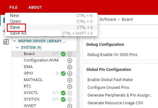
Click SAVE to save the configuration in SYSCONFIG, then turn off SYSCONFIG and return to keil.
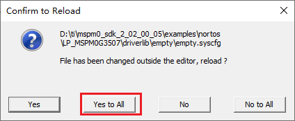
Select Yes to All in the pop-up window
Similarly, we also need to confirm whether the ti_msp_dl_config.c and ti_msp_dl_config.h files are updated. Compile directly, and the compilation will automatically update to keil. If there is no update, we can also copy the file content in SYSCONFIG.
3. Write the program
In the empty.c file, write the following code
x#include "ti_msp_dl_config.h"int main(void){ SYSCFG_DL_init(); //清除定时器中断标志 Clear the timer interrupt flag NVIC_ClearPendingIRQ(TIMER_0_INST_INT_IRQN); //使能定时器中断 Enable timer interrupt NVIC_EnableIRQ(TIMER_0_INST_INT_IRQN); while (1) { }}//定时器的中断服务函数 已配置为1秒的周期//The timer interrupt service function has been configured to a period of 1 secondvoid TIMER_0_INST_IRQHandler(void){ //如果产生了定时器中断 If a timer interrupt occurs switch( DL_TimerG_getPendingInterrupt(TIMER_0_INST) ) { case DL_TIMER_IIDX_ZERO://如果是0溢出中断 If it is 0 overflow interrupt //将LED灯的状态翻转 Flip the LED status DL_GPIO_togglePins(LED1_PORT, LED1_PIN_2_PIN); break; default://其他的定时器中断 Other timer interrupts break; }}4. Compile
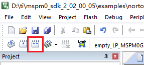
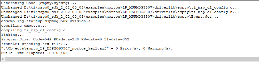
Click the Rebuild icon. The following prompt appears, indicating that the compilation is complete and there are no errors.
4. Program Analysis
- empty.c
xxxxxxxxxx//定时器的中断服务函数 已配置为1秒的周期//The timer interrupt service function has been configured to a period of 1 secondvoid TIMER_0_INST_IRQHandler(void){ //如果产生了定时器中断 If a timer interrupt occurs switch( DL_TimerG_getPendingInterrupt(TIMER_0_INST) ) { case DL_TIMER_IIDX_ZERO://如果是0溢出中断 If it is 0 overflow interrupt //将LED灯的状态翻转 Flip the LED status DL_GPIO_togglePins(LED1_PORT, LED1_PIN_2_PIN); break; default://其他的定时器中断 Other timer interrupts break; }}This is a timer interrupt service program, which is used to handle timer overflow interrupts and perform corresponding operations. Every time the timer overflows, the state of an LED is flipped.
5. Experimental phenomenon
After the program is downloaded, you can see that the LED light is flashing according to the configuration of 1 second period.