Welcome to MSPM0G3507 Development Board repository
11. LCD Display (SPI)
LCD Display (SPI)
LCD Display (SPI)1. Learning ObjectivesSPI ProtocolSPI Hardware InterfaceSPI AdvantagesSPI Determinism2. Hardware Construction3. Experimental steps1. Open the SYSCONFIG configuration tool2. SPI parameter configuration3. Pin parameter configurationLCD screenExternal Flash3. SPI protocol usage4. Write the program5. Compile4. Program Analysis5. Experimental phenomenon
1. Learning Objectives
- Learn the basic knowledge of SPI communication.
- Read the data in the flash and display it on the onboard LCD screen.
SPI Protocol
The SPI protocol (Serial Peripheral Interface) is a commonly used synchronous serial communication protocol designed for high-speed, short-distance communication between microcontrollers and external devices. It supports full-duplex communication, that is, data can be sent and received between the master and slave devices at the same time, and is commonly used in devices such as memory chips, sensors, display drivers, and wireless modules.
SPI Hardware Interface
The SPI protocol usually uses four lines for data transmission:
- SCLK (Serial Clock): The clock signal generated by the master device is used for synchronous communication.
- MOSI (Master Output Slave Input): The master device sends data to the slave device.
- MISO (Master Input Slave Output): The slave device sends data to the master device.
- SS/CS (Slave Select): The master device activates the target slave device through the chip select signal.
SPI Advantages
- Fast communication speed, suitable for high-bandwidth applications.
- Support full-duplex transmission, improve efficiency.
- Simple hardware implementation, direct interface.
- Support multiple slave device connections.
SPI Determinism
- Lack of standardized error detection mechanism.
- The number of master device pins increases with the number of slave devices.
- The communication distance is limited and is usually used for on-board communication.
2. Hardware Construction
W25Q32 is a common serial flash memory device that uses the SPI (Serial Peripheral Interface) interface protocol. It has high-speed read, write and erase functions and is widely used in high-performance electronic devices such as embedded systems, storage devices, routers, etc. The capacity of W25Q32 is 32 Mbit (ie 4 MB), and the numbers in the model represent different capacity options, such as W25Q16, W25Q64, W25Q128, etc., to meet the needs of different application scenarios.
The memory of the W25Q32 chip is allocated by sector (Sector) and block (Block). Specifically:
- Sector: Each sector is 4KB in size.
- Block: Each block contains 16 sectors, i.e., a block is 64KB in size.
These storage unit structures make data management and storage operations more flexible, and are particularly suitable for embedded systems and storage applications that require frequent read and write operations.
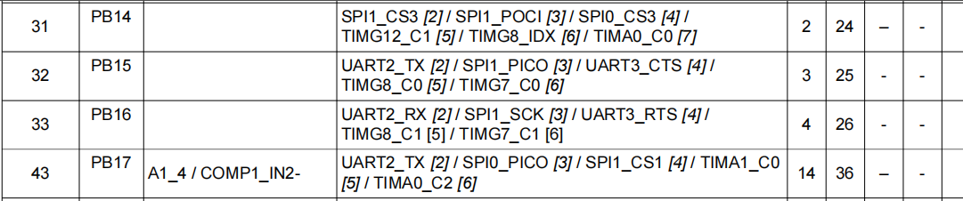
We use the hardware SPI method to drive W25Q32, so we need to determine whether the pin we set has a hardware SPI peripheral interface. In the data sheet, PB14~PB17 can be multiplexed as 4 communication lines of SPI1.
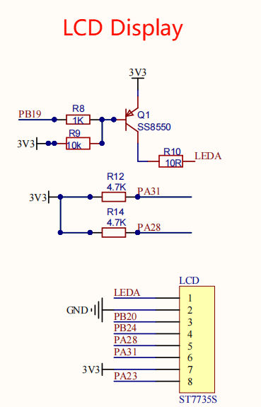
This course does not require additional hardware equipment, and can directly use the onboard LCD screen and external storage flash on the MSPM0G3507 motherboard.
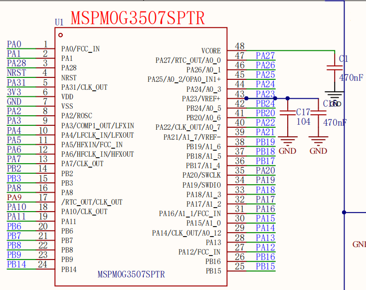
MSPM0G3507 main control diagram:
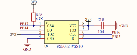
W25Q32 partial schematic diagram:
LCD screen partial schematic diagram:
3. Experimental steps
Here we use the template project we provide for introduction.
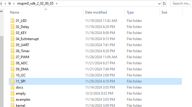
Unzip the template project in the root directory of the SDK, and I rename it to the 11_SPI folder.
1. Open the SYSCONFIG configuration tool
Then open the project.
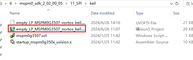
Open the empty.syscfg file in the Keil main interface. With the empty.syscfg file open, open the SYSCONFIG GUI interface.
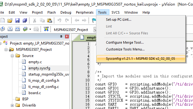
Find the SPI column on the left, click to enter, and add the SPI peripheral.
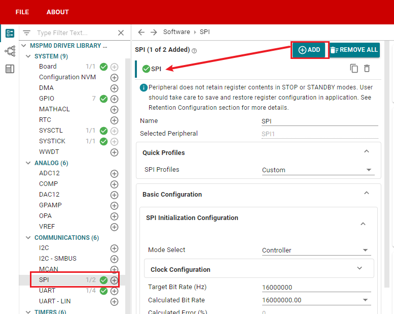
2. SPI parameter configuration
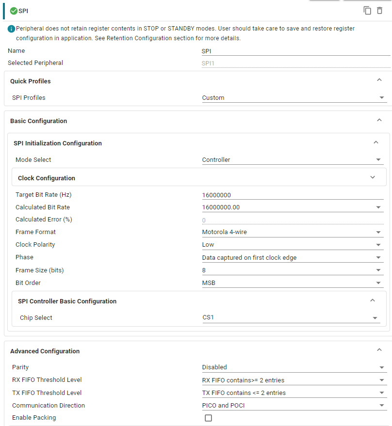
Parameter description:
Mode Select: SPI master-slave mode selection. Select Controller (host) here
Target Bit Rate (Hz): SPI frequency configuration. Fill in 16000000, SPI clock maximum 16MHZ
Calculated Bit Rate: The actual frequency calculated by the software according to the configuration
Calculated Error (%): Calculated frequency error
Frame Format: SPI mode. Select Motorola 4-wire, 4-wire mode
Clock Polarity: SPI clock polarity configuration. Select LoW, polarity is low
Phase: SPI phase configuration. Configured as Data captured on first clock edge, the first phase capture number
Frame Size (bits): Data bit size. Configured as 8-bit data frame
Bit Order: Data order. Configured as MSB, high bit first
Chip Select: Chip select line configuration. Select CS1. It is not important here, we will choose to control CS by software later, not using hardware
Parity: Whether to enable SPI parity. Select Disabled, do not enable
RX FlFo Threshold Level: Configure RX FIFO interrupt trigger level. Configured as RX FlFO contains>= 2 entries
TX FlFo Threshold Level: Configure TX FIFO interrupt trigger level. Configured as TX FlFO contains <= 2 entries
Communication Direction: SPI communication direction. Configured as PICo and PoCl, both sending and receiving
Enable Packing: Whether to enable 32-bit transmission mode. Don't enable it here
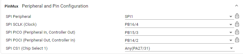
Configure the CS pin casually first, and we will use the software method of CS later.
3. Pin parameter configuration
Find the GPIO column on the left, click to enter, and add several groups of GPIO.
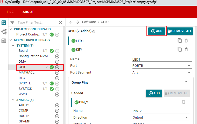
LCD screen
Backlight BLK:
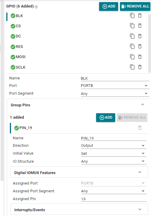
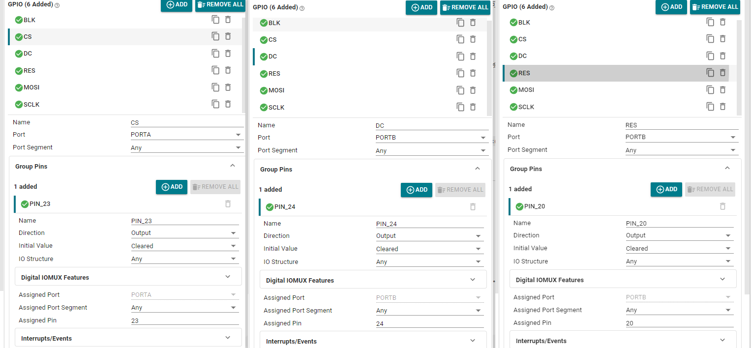
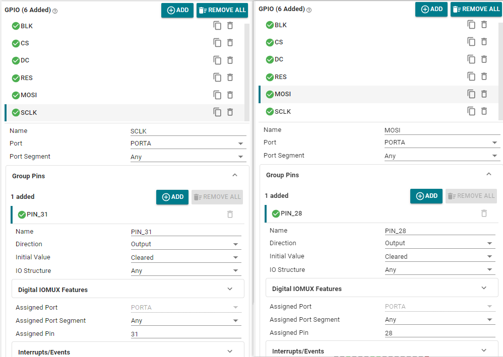
CS, DC, RES, MOSI, SCLK are as follows:
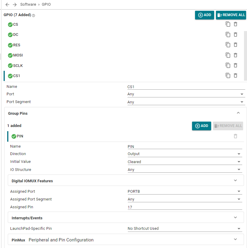
External Flash
CS1
Save and exit.
3. SPI protocol usage
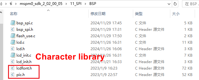
We create four new files in the project template, namely lcd.c, lcd.h, bsp_spi.c and bsp_spi.h. Save them in the BSP folder of the project.
Including the following LCD display drivers and fonts, put them in the BSP folder
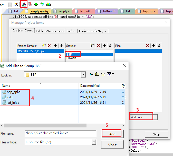
Open the project manager, click BSP, and add the files we created and copied before to the BSP.
Update the header file path.
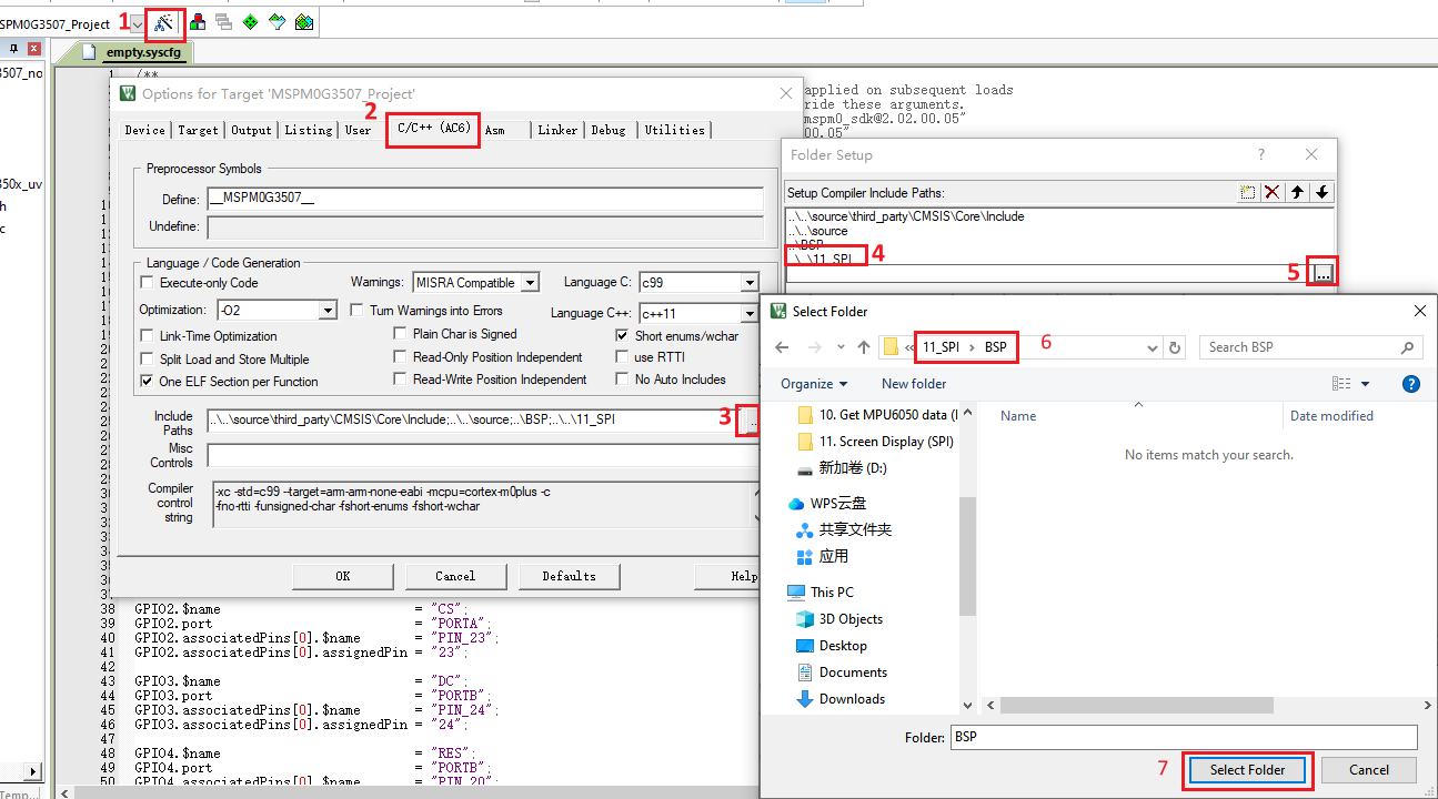
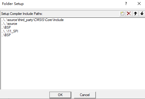
4. Write the program
Define the operation interface and related functions of the LCD display
lcd.h
x#ifndef __LCD_H#define __LCD_H #include <stdint.h>void LCD_Fill(uint16_t xsta,uint16_t ysta,uint16_t xend,uint16_t yend,uint16_t color);//指定区域填充颜色 Specify area fill colorvoid LCD_DrawPoint(uint16_t x,uint16_t y,uint16_t color);//在指定位置画一个点 Draw a point at the specified locationvoid LCD_DrawLine(uint16_t x1,uint16_t y1,uint16_t x2,uint16_t y2,uint16_t color);//在指定位置画一条线 Draw a line at the specified positionvoid LCD_DrawRectangle(uint16_t x1, uint16_t y1, uint16_t x2, uint16_t y2,uint16_t color);//在指定位置画一个矩形 Draw a rectangle at the specified locationvoid Draw_Circle(uint16_t x0,uint16_t y0,uint8_t r,uint16_t color);//在指定位置画一个圆 Draw a circle at the specified locationvoid LCD_ShowChinese(uint16_t x,uint16_t y,uint8_t *s,uint16_t fc,uint16_t bc,uint8_t sizey,uint8_t mode);//显示汉字串 Display Chinese character stringvoid LCD_ShowChinese12x12(uint16_t x,uint16_t y,uint8_t *s,uint16_t fc,uint16_t bc,uint8_t sizey,uint8_t mode);//显示单个12x12汉字 Display a single 12x12 Chinese charactervoid LCD_ShowChinese16x16(uint16_t x,uint16_t y,uint8_t *s,uint16_t fc,uint16_t bc,uint8_t sizey,uint8_t mode);//显示单个16x16汉字 Display a single 16x16 Chinese charactervoid LCD_ShowChinese24x24(uint16_t x,uint16_t y,uint8_t *s,uint16_t fc,uint16_t bc,uint8_t sizey,uint8_t mode);//显示单个24x24汉字 Display a single 24x24 Chinese charactervoid LCD_ShowChinese32x32(uint16_t x,uint16_t y,uint8_t *s,uint16_t fc,uint16_t bc,uint8_t sizey,uint8_t mode);//显示单个32x32汉字 Display a single 32x32 Chinese charactervoid LCD_ShowChar(uint16_t x,uint16_t y,uint8_t num,uint16_t fc,uint16_t bc,uint8_t sizey,uint8_t mode);//显示一个字符 Display a charactervoid LCD_ShowString(uint16_t x,uint16_t y,const uint8_t *p,uint16_t fc,uint16_t bc,uint8_t sizey,uint8_t mode);//显示字符串 Display Stringuint32_t mypow(uint8_t m,uint8_t n);//求幂 Powervoid LCD_ShowIntNum(uint16_t x,uint16_t y,uint16_t num,uint8_t len,uint16_t fc,uint16_t bc,uint8_t sizey);//显示整数变量 Display integer variablesvoid LCD_ShowFloatNum1(uint16_t x,uint16_t y,float num,uint8_t len,uint16_t fc,uint16_t bc,uint8_t sizey);//显示两位小数变量 Display variables with two decimal placesvoid LCD_ShowPicture(uint16_t x,uint16_t y,uint16_t length,uint16_t width,const uint8_t pic[]);//显示图片 Show image//画笔颜色 Brush Color#define WHITE 0xFFFF#define BLACK 0x0000 #define BLUE 0x001F #define BRED 0XF81F#define GRED 0XFFE0#define GBLUE 0X07FF#define RED 0xF800#define MAGENTA 0xF81F#define GREEN 0x07E0#define CYAN 0x7FFF#define YELLOW 0xFFE0#define BROWN 0XBC40 //棕色 Brown#define BRRED 0XFC07 //棕红色 Brown red#define GRAY 0X8430 //灰色 Gray#define DARKBLUE 0X01CF //深蓝色 Dark blue#define LIGHTBLUE 0X7D7C //浅蓝色 Light blue#define GRAYBLUE 0X5458 //灰蓝色 Gray blue#define LIGHTGREEN 0X841F //浅绿色 Light green#define LGRAY 0XC618 //浅灰色(PANNEL),窗体背景色 Light gray (PANNEL), window background color#define LGRAYBLUE 0XA651 //浅灰蓝色(中间层颜色) Light gray blue (middle layer color)#define LBBLUE 0X2B12 //浅棕蓝色(选择条目的反色) Light brown blue (inverted color of selected item)#endifNext is the LCD display driver
lcd.c (only part of it is captured here, please check the project source code for details)
xxxxxxxxxx#include "lcd.h"#include "lcd_init.h"#include "lcdfont.h"#include "board.h"/****************************************************************************** 函数说明:在指定区域填充颜色 入口数据:xsta,ysta 起始坐标 xend,yend 终止坐标 color 要填充的颜色 返回值: 无 Function description: Fill the specified area with color Input data: xsta, ysta starting coordinates xend, yend ending coordinates color the color to be filled Return value: None******************************************************************************/void LCD_Fill(uint16_t xsta,uint16_t ysta,uint16_t xend,uint16_t yend,uint16_t color){ uint16_t i,j; LCD_Address_Set(xsta,ysta,xend-1,yend-1);//设置显示范围 Set the display range for(i=ysta;i<yend;i++) { for(j=xsta;j<xend;j++) { LCD_WR_DATA(color); } } }/****************************************************************************** 函数说明:在指定位置画点 入口数据:x,y 画点坐标 color 点的颜色 返回值: 无 Function description: Draw a point at the specified position Input data: x, y coordinates of the point color color of the point Return value: None******************************************************************************/void LCD_DrawPoint(uint16_t x,uint16_t y,uint16_t color){ LCD_Address_Set(x,y,x,y);//设置光标位置 Set the cursor position LCD_WR_DATA(color);} ...bsp_spi.h
xxxxxxxxxx#ifndef _BSP_SPI_H__#define _BSP_SPI_H__#include "board.h"//CS引脚的输出控制//x=0时输出低电平//x=1时输出高电平//CS pin output control//x=0 when output is low level//x=1 when output is high level#define SPI_CS(x) ( (x) ? DL_GPIO_setPins(CS1_PORT,CS1_PIN_17_PIN) : DL_GPIO_clearPins(CS1_PORT,CS1_PIN_17_PIN) )uint16_t W25Q32_readID(void);//读取W25Q32的ID Read the ID of W25Q32void W25Q32_write(uint8_t* buffer, uint32_t addr, uint16_t numbyte); //W25Q32写数据 W25Q32 write datavoid W25Q32_read(uint8_t* buffer,uint32_t read_addr,uint16_t read_length);//W25Q32读数据 W25Q32 Read Data#endifThe initialization of SPI has been configured in SYSCONFIG, but we still need to prepare the SPI read and write steps. To ensure the success of sending and receiving data, when sending, you need to ensure that the data in the send buffer is sent, that is, the send buffer is empty, before the next data can be sent; when receiving, you need to ensure that there is data in the receive buffer before receiving.
bsp_spi.c (only part of it is intercepted here, please refer to the project source code for details)
xxxxxxxxxx#include "bsp_spi.h"uint8_t spi_read_write_byte(uint8_t dat){ uint8_t data = 0; //发送数据 Sending Data DL_SPI_transmitData8(SPI_INST,dat); //等待SPI总线空闲 Wait for the SPI bus to be idle while(DL_SPI_isBusy(SPI_INST)); //接收数据 Receiving Data data = DL_SPI_receiveData8(SPI_INST); //等待SPI总线空闲 Wait for the SPI bus to be idle while(DL_SPI_isBusy(SPI_INST)); return data;}...Then write the following code in the empty.c file
xxxxxxxxxx#include "ti_msp_dl_config.h"#include "board.h"#include "lcd_init.h"#include "lcd.h"#include "pic.h"#include "bsp_spi.h"#include <stdint.h>#include <stdio.h>int main(void){ unsigned char buff[10] = {0}; //开发板初始化 Development board initialization board_init(); delay_ms(100);//等待部署 Waiting for deployment //读取W25Q32的ID Read the ID of W25Q32 printf("ID = %X\r\n",W25Q32_readID()); //读取0地址的5个字节数据到buff Read 5 bytes of data from address 0 to buff W25Q32_read(buff, 0, 7); //串口输出读取的数据 Serial port outputs the read data printf("buff = %s\r\n",buff); //往0地址写入5个字节长度的数据 ABCD Write 5 bytes of data ABCD to address 0 W25Q32_write("Yahboom", 0, 7); delay_ms(100); //读取0地址的5个字节数据到buff Read 5 bytes of data from address 0 to buff W25Q32_read(buff, 0, 7); //串口输出读取的数据 Serial port outputs the read data // printf("buff = %s\r\n",buff); SYSCFG_DL_init(); LCD_Init();//LCD初始化 LCD Initialization LCD_Fill(0,0,LCD_W,LCD_H,WHITE); LCD_ShowPicture(20,45,120,29,gImage_pic1); LCD_ShowString(10,0,"Hello!",BLACK,WHITE,16,0); // 显示 buff 中的内容在同一行上 Display the contents of buff on the same line int x = 54; // 起始 x 坐标 Starting x coordinate for (int i = 0; i < 7; i++) { char str[2] = {buff[i], '\0'}; // 每次取一个字符 Take one character at a time LCD_ShowString(x, 25, str,BLACK, WHITE, 16, 0); // 显示字符 Display Characters x += 8; // 每个字符的宽度为 8,x 坐标向右偏移 Each character is 8 wide and has an x-coordinate offset to the right. } while (1) { }}5. Compile
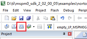
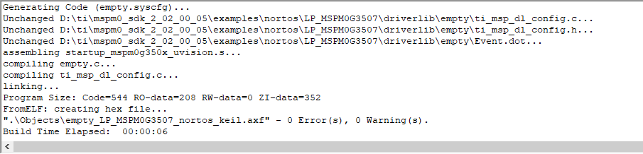
Click the Rebuild icon. The following prompt appears, indicating that the compilation is complete and there are no errors.
4. Program Analysis
- lcd.c
xxxxxxxxxx/****************************************************************************** 函数说明:在指定区域填充颜色 入口数据:xsta,ysta 起始坐标 xend,yend 终止坐标 color 要填充的颜色 返回值: 无 Function description: Fill the specified area with color Input data: xsta, ysta starting coordinates xend, yend ending coordinates color the color to be filled Return value: None******************************************************************************/void LCD_Fill(uint16_t xsta,uint16_t ysta,uint16_t xend,uint16_t yend,uint16_t color){ uint16_t i,j; LCD_Address_Set(xsta,ysta,xend-1,yend-1);//设置显示范围 Set the display range for(i=ysta;i<yend;i++) { for(j=xsta;j<xend;j++) { LCD_WR_DATA(color); } } }The LCD_Fill function fills the specified color in the area between the specified starting coordinates (xsta, ysta) and the ending coordinates (xend, yend). It completes the area filling operation by setting the display range and looping to write color data.
xxxxxxxxxx/****************************************************************************** 函数说明:显示图片 入口数据:x,y起点坐标 length 图片长度 width 图片宽度 pic[] 图片数组 返回值: 无 Function description: Display image Input data: x, y starting point coordinates length Image length width Image width pic[] Image array Return value: None******************************************************************************/void LCD_ShowPicture(uint16_t x,uint16_t y,uint16_t length,uint16_t width,const uint8_t pic[]){ uint16_t i,j; uint32_t k=0; LCD_Address_Set(x,y,x+length-1,y+width-1); for(i=0;i<length;i++) { for(j=0;j<width;j++) { LCD_WR_DATA8(pic[k*2]); LCD_WR_DATA8(pic[k*2+1]); k++; } } }The LCD_ShowPicture function draws the picture at the specified starting point (x, y), sets the display area according to the given length and width, and writes the color data of each pixel to the LCD by traversing the picture array to complete the picture display.
xxxxxxxxxx/****************************************************************************** 函数说明:显示字符串 入口数据:x,y显示坐标 *p 要显示的字符串 fc 字的颜色 bc 字的背景色 sizey 字号 mode: 0非叠加模式 1叠加模式 返回值: 无 Function description: Display string Input data: x, y display coordinates *p string to be displayed fc color of the word bc background color of the word sizey font size mode: 0 non-overlay mode 1 overlay mode Return value: None******************************************************************************/void LCD_ShowString(uint16_t x,uint16_t y,const uint8_t *p,uint16_t fc,uint16_t bc,uint8_t sizey,uint8_t mode){ while(*p!='\0') { LCD_ShowChar(x,y,*p,fc,bc,sizey,mode); x+=sizey/2; p++; } }The LCD_ShowString function is used to display a string at the specified coordinates (x, y), and calls the LCD_ShowChar function in sequence to draw each character in the string. At the same time, the character spacing is adjusted according to the font size. Both overlay mode and non-overlay mode display are supported.
xxxxxxxxxx/****************************************************************************** 函数说明:显示汉字串 入口数据:x,y显示坐标 *s 要显示的汉字串 fc 字的颜色 bc 字的背景色 sizey 字号 可选 16 24 32 mode: 0非叠加模式 1叠加模式 返回值: 无 Function description: Display Chinese character string Input data: x, y display coordinates *s Chinese character string to be displayed fc character color bc character background color sizey font size optional 16 24 32 mode: 0 non-overlay mode 1 overlay mode Return value: None******************************************************************************/void LCD_ShowChinese(uint16_t x,uint16_t y,uint8_t *s,uint16_t fc,uint16_t bc,uint8_t sizey,uint8_t mode){ while(*s!=0) { LCD_ShowChinese16x16(x,y,s,fc,bc,sizey,mode); s+=2; x+=sizey; }}The LCD_ShowChinese function is used to display a Chinese character string at the specified coordinates (x, y). It draws each Chinese character by calling the LCD_ShowChinese16x16 function one by one and adjusts the display position of the next Chinese character according to the font size. It supports both overlay mode and non-overlay mode display.
- bsp_spi.c
xxxxxxxxxx/********************************************************** * 函 数 名 称:W25Q32_read * 函 数 功 能:读取W25Q32的数据 * 传 入 参 数:buffer=读出数据的保存地址 read_addr=读取地址 read_length=读去长度 * 函 数 返 回:无 * 作 者:LC * 备 注:无 * Function name: W25Q32_read * Function function: Read W25Q32 data * Input parameters: buffer = storage address of read data read_addr = read address read_length = read length * Function return: None * Author: LC * Notes: None**********************************************************/void W25Q32_read(uint8_t* buffer,uint32_t read_addr,uint16_t read_length){ uint16_t i; //拉低CS端为低电平 Pull the CS end to a low level SPI_CS(0); //发送指令03h Send instruction 03h spi_read_write_byte(0x03); //发送24位读取数据地址的高8位 // Send the high 8 bits of the 24-bit read data address spi_read_write_byte((uint8_t)((read_addr)>>16)); //发送24位读取数据地址的中8位 // Send the middle 8 bits of the 24-bit read data address spi_read_write_byte((uint8_t)((read_addr)>>8)); //发送24位读取数据地址的低8位 // Send the low 8 bits of the 24-bit read data address spi_read_write_byte((uint8_t)read_addr); //根据读取长度读取出地址保存到buffer中 // Read the address according to the read length and save it in the buffer for(i=0;i<read_length;i++) { buffer[i]= spi_read_write_byte(0XFF); } //恢复CS端为高电平 Restore the CS end to a high level SPI_CS(1);}The W25Q32_read function is used to read data from the W25Q32 flash chip. The function first starts SPI communication by pulling the CS pin low, then sends the read command (0x03) and the high, middle, and low bytes of the read address. Next, the data is read byte by byte and stored in the provided buffer (buffer) according to the specified read length. Finally, the function restores the CS pin to a high level to end the data transfer. This process ensures that the specified length of data is read from the specified address.
xxxxxxxxxx/********************************************************** * 函 数 名 称:W25Q32_write * 函 数 功 能:写数据到W25Q32进行保存 * 传 入 参 数:buffer=写入的数据内容 addr=写入地址 numbyte=写入数据的长度 * 函 数 返 回:无 * 作 者:LC * 备 注:无 * Function name: W25Q32_write * Function function: Write data to W25Q32 for storage * Input parameters: buffer = data content to be written addr = write address numbyte = length of written data * Function return: None * Author: LC * Notes: None**********************************************************/void W25Q32_write(uint8_t* buffer, uint32_t addr, uint16_t numbyte){ unsigned int i = 0; //擦除扇区数据 Erase sector data W25Q32_erase_sector(addr/4096); //写使能 Write enable W25Q32_write_enable(); //忙检测 Busy detection W25Q32_wait_busy(); //写入数据 Write data //拉低CS端为低电平 Pull CS to low level SPI_CS(0); //发送指令02h Send instruction 02h spi_read_write_byte(0x02); //发送写入的24位地址中的高8位 // Send the high 8 bits of the 24-bit address to be written spi_read_write_byte((uint8_t)((addr)>>16)); //发送写入的24位地址中的中8位 // Send the middle 8 bits of the 24-bit address to be written spi_read_write_byte((uint8_t)((addr)>>8)); //发送写入的24位地址中的低8位 // Send the low 8 bits of the 24-bit address to be written spi_read_write_byte((uint8_t)addr); //根据写入的字节长度连续写入数据buffer // Continuously write data buffer according to the length of the written byte for(i=0;i<numbyte;i++) { spi_read_write_byte(buffer[i]); } //恢复CS端为高电平 Restore CS end to high level SPI_CS(0); //忙检测 Busy detection W25Q32_wait_busy();}The W25Q32_write function is used to write data to the W25Q32 flash chip. First, the function erases the sector data at the target address. Then, it enables the write operation and checks if the chip is busy. Next, the function sends a write command (0x02) and a data address (24-bit address) to the chip through the SPI interface, and writes the data byte by byte according to the specified write length. Finally, the function waits for the write operation to complete and restores the CS pin to a high level to ensure that the data is written correctly and the chip is in an idle state.
- empty.c
xxxxxxxxxxint main(void){ unsigned char buff[10] = {0}; //开发板初始化 Development board initialization board_init(); delay_ms(100);//等待部署 Waiting for deployment //读取W25Q32的ID Read the ID of W25Q32 printf("ID = %X\r\n",W25Q32_readID()); //读取0地址的5个字节数据到buff Read 5 bytes of data from address 0 to buff W25Q32_read(buff, 0, 7); //串口输出读取的数据 Serial port outputs the read data printf("buff = %s\r\n",buff); //往0地址写入5个字节长度的数据 ABCD Write 5 bytes of data ABCD to address 0 W25Q32_write("Yahboom", 0, 7); delay_ms(100); //读取0地址的5个字节数据到buff Read 5 bytes of data from address 0 to buff W25Q32_read(buff, 0, 7); //串口输出读取的数据 Serial port outputs the read data // printf("buff = %s\r\n",buff); SYSCFG_DL_init(); LCD_Init();//LCD初始化 LCD Initialization LCD_Fill(0,0,LCD_W,LCD_H,WHITE); LCD_ShowPicture(20,45,120,29,gImage_pic1); LCD_ShowString(10,0,"Hello!",BLACK,WHITE,16,0); // 显示 buff 中的内容在同一行上 Display the contents of buff on the same line int x = 54; // 起始 x 坐标 Starting x coordinate for (int i = 0; i < 7; i++) { char str[2] = {buff[i], '\0'}; // 每次取一个字符 Take one character at a time LCD_ShowString(x, 25, str,BLACK, WHITE, 16, 0); // 显示字符 Display Characters x += 8; // 每个字符的宽度为 8,x 坐标向右偏移 Each character is 8 wide and has an x-coordinate offset to the right. } while (1) { }}The main functions of this program are to initialize the development board, read and write data from the W25Q32 flash chip, and display the read content through the LCD. First, the program initializes the development board and related hardware. Then, it reads the chip ID of the W25Q32 and outputs it through the serial port. Next, the program reads 7 bytes of data from the starting address (address 0) of the flash memory to the buff array and outputs this data through the serial port. Next, it writes the string "Yahboom" to address 0 of the flash memory and reads and displays this data again. Finally, the program initializes the LCD screen, displays a welcome message and a picture, and displays the read buff data character by character on the same line of the screen.
5. Experimental phenomenon
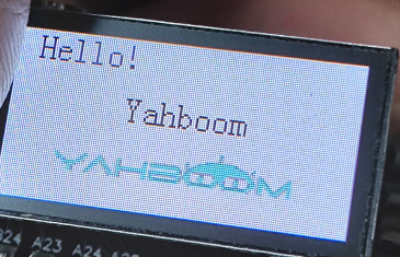
After the program is downloaded, the text "Hello!", the data in the flash, and the Yahboom logo will be displayed in lines on the LCD display.