yahboom
HomeLearn
Solution
Blog
Online Store
About Us
EN/中文
ROSMASTER X3📖
1.About ROSMASTER X3
  • 1.1 Wiring Introduction
  • 1.2 Precautions for battery
  • 1.3 First Trial
2.Assembly steps
  • Installation Video(1-10)
  • Installation Video(11-18)
  • Installation Video(20-28)
  • Installation Video(29-30)
3.ROS1-Remote control course
  • 3.1 APP remote control
  • 3.2 Model aircraft remote control
  • 3.3 Handle remote control
4.ROS1-Hardware course
  • 4.1 About expansion board_V3.0
  • 4.1 About expansion board_V1.0
  • 4.2 STM32 Development environment
  • 4.3 Button to control the buzzer to whistle
  • 4.4 FreeRTOS application
  • 4.5 Serial communication
  • 4.6 SBUS model aircraft remote control
  • 4.7 CAN bus communication
  • 4.8 RGB colorful light bar
  • 4.9 Timer interrupt to control PWM servo
  • 4.10 Control serial port servos
  • 4.11 Nine-axis attitude sensor to obtain data
  • 4.12 Control motor
  • 4.13 Timer captures the encoder data
  • 4.14.1 Kinematic Analysis of Mecanum Wheel
  • 4.14.2 Kinematics Analysis of Ackermann Car
  • 4.15 PID control robot movement
5.ROS1-Basic course
  • 5.1 Update the firmware
  • 5.2 Turn off the self-starting process at startup
  • 5.3 Install the Rosmaster driver library
  • 5.4 Buzzer whistle
  • 5.5 Control PWM servo
  • 5.6 RGB colorful light bar special effects display
  • 5.7 Control motor
  • 5.8 Control robot movement
  • 5.9 Control Serial Servo
6.ROS1-Linux operating system
  • 6.1 Virtual machine installation and use
  • 6.2 Linux basics
  • 6.3 Remote control
  • 6.4 Multi-machine communication configuration
  • 6.5 Static IP and hotspot mode
  • 6.6 Bind the device ID
  • 6.7 Web page real-time monitoring
  • 6.8 Expansion tutorial
  • 6.9.1 Jetson Nano write sytem
  • 6.9.2 Jetson Xavier NX write system
  • 6.9.3 Jetson TX2 NX write system
  • 6.9.4 Raspberry Pi write system
7.ROS1-Docker-pi5
  • 1、Docker overview and docker installation
  • 2、Common commands for docker image containers
  • 3、Docker images deeply understand and publish images
  • 4、Docker hardware interaction and data processing
  • 5、Enter the bot's docker container
  • 6、Robot development environment construction in Docker
  • 7、How customers can update docker images in the future
8.ROS1-ROS basic course
  • 1.ROS introduction
  • 2.ROS installation
  • 3.ROS common command tools
  • 4.ROS workspace
  • 5.ROS function package
  • 6.ROS node
  • 7.ROS topic publisher
  • 8.ROS topic subscribers
  • 9.ROS service client
  • 10.ROS service server
  • 11.ROS action client
  • 12.ROS action server
  • 13.ROS custom message reception
  • 14.ROS-launch file
  • 15.ROS-TF transformation
  • 16.ROS parameter service
  • 17.ROS-rviz use
  • 18.ROS-rqt tool usage
  • 19.Topic message recording and playback
  • 20.urdf model introduction
  • 21.gazebo introduction
  • 22.ROS distributed communication
9.ROS1-OpenCV courses
  • 9.1 Getting started with Open Source CV
  • 9.2 Geometric transformation
  • 9.3 Image processing and drawing text line segments
  • 9.4 Image beautification
  • 9.5 Opencv application
  • 9.6 AR vision
  • 9.7 AR QR code
  • 9.8 ROS+Opencv foundation
  • 9.9 ROS+Opencv application
  • 9.10 Data transformation and point cloud
  • 9.11 MediaPipe development
10.ROS1-Robot control course
  • 10.1 PID algorithm theory
  • 10.2 Robot PID debugging
  • 10.3 Robot information release
  • 10.4 Robot keyboard control
  • 10.5 Robot handle control
  • 10.6 Robot state estimation
  • 10.7 Robot calibration
  • 10.8 Robot URDF model
11.ROS1-Depth camera course
  • 11.1 How to use the Astra camera
  • 11.2 Astra camera calibration
  • 11.3 Astra Color Tracking
  • 11.4 Astra Object Tracking
  • 11.5 Visual tracking autopilot
  • 11.6 Pure visual 2D mapping and navigation
  • 11.7 RTAB-Map 3D mapping navigation
  • 11.8 ORB_SLAM2 basics
  • 11.9 ORB_SLAM2_Octomap
12.ROS1-Lidar course
  • 12.1 Lidar basic-SLAM
  • 12.1 Lidar basic-4ROS
  • 12.2 Lidar avoiding
  • 12.3 Lidar guard
  • 12.4 Lidar follow
  • 12.5 Patrol game
  • 12.6 gmapping mapping algorithm
  • 12.7 hector mapping algorithm
  • 12.8 karto mapping algorithm
  • 12.9 cartographer mapping algorithm
  • 12.10 rrt_exploration mapping algorithm
  • 12.11 AMCL
  • 12.12 Navigation and avoiding
  • 12.13 APP mapping and navigation
13.ROS1-Multi-robot control course
  • 13.1 Multi-machine handle control
  • 13.2 Multi-machine navigation
  • 13.3 Multi-machine formation
  • 13.4 Multi-machine surround
14.ROS1-Deep learning courses
  • 14.1 KNN recognizes handwritten digits
  • 14.2 Basic use of TensorFlow
  • 14.3 Basic use of PyTorch(jetson)
  • 14.4 yolov5 model training(jetson)
  • 14.5 yolov5+tensorrt acceleration(jetson)
  • 14.6 yolov4-tiny
15.ROS1-Voice control courses
  • 15.0 How to use old voice module in new image
  • 15.1 Introduction of voice control module-NEW
  • 15.2 Voice control module port binding-NEW
  • 15.1 Introduction of voice control module-Old
  • 15.2 Voice control module port binding-Old
  • 15.3 Voice control car movement
  • 15.4 Voice control Autopilot
  • 14.5 Voice control color recognition
  • 15.6 Voice control color tracking
  • 15.7 Voice control multi-point navigation
16.ROS1-Model training Autopilot
  • 16.0 ReadMe
  • 16.1 yolov5 to train traffic signs
  • 16.2 TensorRt acceleration identification mark
  • 16.3 Road sign indication function description
  • 16.4 Collect data
  • 16.5 Training model
  • 16.6 Model transformation and application
  • 16.7 AI Autopilot
17.ROS2- Remote control course
  • 1. APP control
  • 2. Model aircraft control
  • 3. Wireless Handle Control Tutorial
18.ROS2- Hardware course
  • 1. About expansion board_V1.0
  • 1. About expansion board_V3.0
  • 2. STM32 Development environment
  • 3. Button control
  • 4. FreeRTOS application
  • 5. Serial communication
  • 6. SBUS model aircraft remote control
  • 7. CAN bus communication
  • 8. RGB colorful light bar
  • 9. Timer interrupt to control PWM servo
  • 10. Control serial port servos
  • 11. Nine-axis attitude sensor to obtain data
  • 12. Control motor
  • 13. Timer captures the encoder data
  • 14. Robot kinematics analysis theory
  • 15. PID control robot movement
19.ROS2- ROSMASTER basic course
  • 1. Update the firmware
  • 2. Turn off the self-starting process at startup
  • 3. Install the Rosmaster driver library
  • 4. Buzzer whistle
  • 5. Control PWM servo
  • 6. RGB colorful light bar special effects display
  • 7. Control motor
  • 8. Control robot movement
  • 9. Control Serial Servo
20.ROS2- Linux operating systemnew
  • 1. Virtual machine installation and use
  • 2. Linux basics
  • 3. Remote control
  • 4. Multi-machine communication configuration
  • 5. Static IP and hotspot mode
  • 6. Bind the device ID
  • 7. Web page real-time monitoring
  • 8. Expansion tutorial
  • 9.1 Jetson Nano write sytem
  • 9.2 Raspberry Pi write system
  • 9.3 Orin series write system
  • 10.Jetpack old system upgraded to SUPER systemnew
21.ROS2- Docker(Nano Pi)
  • 1. Docker Overview and Docker Installation
  • 2.Common commands for docker image containers
  • 3.Docker images deeply understand and publish images
  • 4. Docker hardware interaction and data processing
  • 5. Entering the Docker Container of the Robot
  • 6. Building a Robot Development Environment in Docker
  • 7. Method for customers to update Docker images in the future
22.ROS2- ROS2 Basic Tutorial
  • 1.Introduction to ROS2
  • 2.ROS2 install Humble
  • 3.ROS2 development environment
  • 4.ROS2 workspace
  • 5.ROS2 function package
  • 6.ROS2 node
  • 7.ROS2 topic communication
  • 8.ROS2 service communication
  • 9.ROS2 action communication
  • 10.ROS2 custom interface message
  • 11.ROS2 parameter service case
  • 12.ROS2 meta-function package
  • 13.ROS2 distributed communication
  • 14.ROS2 DDS
  • 15.ROS2 time related API
  • 16.ROS2 common command tools
  • 17.ROS2 rviz2 use
  • 18.ROS2 Rqt Toolbox
  • 19.ROS2 Launch startup file configuration
  • 20.ROS2 recording and playback tool
  • 21.ROS2 URDF model
  • 22.ROS2 Gazebo simulation platform
  • 23.ROS2 TF2 coordinate transformation
23.ROS2- Robot control course
  • 1. PID Algorithm Theory
  • 2. Robot information release
  • 3. Robot control
  • 4. Robot state estimation
  • 5. Robot calibration
  • 6. URDF model
24.ROS2- Depth camera course
  • 1.Depth camera usage
  • 2. Camera internal reference calibration
  • 3. color tracking
  • 4. KCF object tracking
  • 5. ORB_SLAM2 basics
  • 6. ORB_ SLAM2 PCL mapping
  • 7. ORB_ SLAM2 Octomap mapping
  • 8. RTAB-Map 3D mapping navigation
25.ROS2- Lidar course
  • 1. Introduction and Use of Lidar
  • 2. Lidar avoiding
  • 3. Lidar follow
  • 4. Lidar guard
  • 5. Patrol game
  • 6. Gmapping mapping algorithm
  • 7. Cartographer mapping algorithm
  • 8. Navigation and obstacle avoidance
  • 9. Rosmaster_ X3 conducts mapping through the APP
  • 10. Rosmaster_ X3 Navigation through APP
26.ROS2- OpenCV courses
  • 1. OpenCV Basic Course
  • 2. ROS+opencv application
  • 3. QR code creation and recognition
  • 4. AR Vision
  • 5. Mediapipe fun gameplay
  • 6、line patrol automatic driving
27.ROS2- Voice control courses
  • 0.How to use old voice module in new image
  • 1. Introduction of voice module-new
  • 2. Voice control module port binding-new
  • 1. Introduction of voice module and port binding-old
  • 3. Voice control car movement
  • 4. Voice control Autopilot
  • 5. Voice control color recognition
  • 6. Voice control color tracking
  • 7. Voice control multi-point navigation
28.Deep learning courses(SUPER)
  • 1.KNN recognizes handwritten digitsnew
  • 2.Basic use of TensorFlownew
  • 3.Basic use of PyTorch(jetson)new
  • 4.YOLOv11Model conversion(SUPER)new
  • 5.YOLOv11Dataset annotation(SUPER)new
  • 6.YOLOv11Model conversion + tensorrt acceleration(SUPER)new
  • 7.YOLOv11Object recognition(SUPER)new
29.ROS2-Multi-robot control
  • 1. Multi-robot control
  • 2. Multi-robot navigation
LLM tutorial
1.Development environment
  • 0. Model usage instructions
  • 1.Environments deployment
  • 2.Dialogue platform installation
2.Jetson Nano B01
  • 1.Qwen2 model
  • 2.TinyLlama model
  • 3.Phi-3 model
  • 4.Gemma model
  • 5.Orca Mini model
  • 6.StarCoder2 model
  • 7.DeepSeek-R1 model
  • 8.Expand LLaVA-Phi3
3.Jetson Orin NXNANO
  • 1.Llama3 model
  • 2.Qwen2 model
  • 3.Phi-3 model
  • 4.Gemma model
  • 5.WizardLM2 model
  • 6.Codellama model
  • 7.DeepSeek-R1 model
  • 8.Orca Mini model
  • 9.StarCoder2 model
  • 10.TinyLlama model
  • 11.Expand LLaVA
  • 12.Expand LLaVA-Phi3
4.Raspberry Pi 5B
  • 1.Meta AI Llama3 model
  • 2.Qwen2 model
  • 3.Phi-3 model
  • 4.Gemma model
  • 5.WizardLM2 model
  • 6.Meta AI Codellama model
  • 7.DeepSeek-R1 model
  • 8.Expand LLaVA
FAQ
  • 1.Using your own Jetson board, ROSMASTER X3 cannot start normally
Download
  • RemoteCtrl_APP(Android/iOS)
  • Mapping_APP(iOS_Android)
  • Instruction Manual
  • SystemFile_ROS2
  • SystemFile_ROS1
  • SystemFile_ROS2_OrinNANOSUPER
  • SystemFile_ROS2_OrinNXSUPER
  • Code
  • Jetson_Boot_USB.tar.gz
  • VM software
  • Autopilot Annex
  • Other_Annex_File
  • LLM_SystemFile
  • ROS2_Basic_VM
Download ZIP
FAQ
  • 1、How to connect OLED?

Welcome to ROSMASTER X3 repository

11.5 Visual tracking autopilot

5. Astra autonomous driving

5. Astra autonomous driving5.1. Introduction5.1.1, HSV introduction5.1.2, HSV hexagonal pyramid5.2. Operation steps5.2.1. Start5.2.2. Identification5.2.3. Color calibration5.2.4. Tracking driving

Function package: ~/yahboomcar_ws/src/yahboomcar_linefollw

5.1. Introduction

The Yahboom mobile robot's depth camera is capable of autonomous driving. It can recognize multiple colors at any time, independently store the currently recognized colors, and follow the detected and recognized colors. During the tracking process, it can also achieve real-time obstacle avoidance.

The Yahboom mobile robot can also realize the function of real-time control of HSV. By adjusting the high and low thresholds of HSV, it filters out interfering colors, so that the tracking route can be ideally identified in complex environments. If the color selection effect is not ideal, If so, you need to move the car to different environments and calibrate it at this time, so that it can recognize the colors we need in complex environments.

5.1.1, HSV introduction

HSV (Hue, Saturation, Value) is a color space created by A. R. Smith in 1978 based on the intuitive characteristics of color, also known as the Hexcone Model.

The parameters of color in this model are: hue (H), saturation (S), and lightness (V).

H: 0 — 180

S: 0 — 255

V: 0 — 255

Here some reds are classified into the purple range:

image-20210908180521035

5.1.2, HSV hexagonal pyramid

  • Hue H

Represents color information, that is, the position of the spectral color. This parameter is represented by an angle, with a value ranging from 0° to 360°, starting from red and counting in counterclockwise direction. Red is 0°, green is 120°, and blue is 240°. Their complementary colors are: yellow is 60°, cyan is 180°, and purple is 300°.

  • Saturation S

Saturation S is expressed as the ratio between the purity of the selected color and the maximum purity of that color. When S=0, there is only grayscale. 120 degrees apart. Complimentary colors are 180 degrees apart. A color can be thought of as the result of mixing a certain spectral color with white. The greater the proportion of spectral colors, the closer the color is to spectral colors, and the higher the saturation of the color. The saturation is high and the color is deep and vivid. The white light component of the spectral color is 0, and the saturation reaches the highest level. Usually the value range is 0% ~ 100%. The larger the value, the more saturated the color.

  • LightnessV

Brightness represents the brightness of a color. For light source color, the brightness value is related to the brightness of the luminous body; for object color, this value is related to the transmittance or reflectance of the object. Usually the value range is 0% (black) to 100% (white). One thing to note: there is no direct relationship between it and light intensity.

The three-dimensional representation of the HSV model evolves from the RGB cube. If you imagine looking from the white vertices of the RGB along the diagonal of the cube to the black vertices, you can see the hexagonal shape of the cube. The hexagonal borders represent color, the horizontal axis represents purity, and lightness is measured along the vertical axis.

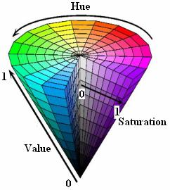
image-20210908180542250image-20210908180549330

5.2. Operation steps

5.2.1. Start

Note: [R2] on the remote control handle has the [pause/start] function for this gameplay. Different models will have different parameter ranges, but the principle is the same; take the X3 McLunner as an example.

There are two starting methods, choose one. The demonstration case is method 2; before starting, place the robot to the starting position so that the depth camera faces downward as much as possible.

xxxxxxxxxx
#Raspberry Pi 5 master needs to enter docker first, please perform this step
#If running the script into docker fails, please refer to ROS/07, Docker tutorial
~/run_docker.sh

method one

robot side

xxxxxxxxxx
roslaunch yahboomcar_linefollw follow_line.launch VideoSwitch:=true img_flip:=false

Method 2

Can be controlled remotely for easy operation.

robot side

xxxxxxxxxx
roslaunch yahboomcar_linefollw follow_line.launch VideoSwitch:=false img_flip:=false

virtual machine

xxxxxxxxxx
roslaunch yahboomcar_linefollw line.launch
  • VideoSwitch parameter: whether to use the camera function package to start.

  • img_flip parameter: whether to flip the screen horizontally, the default is false.

Set parameters according to needs, or modify the launch file directly, so there is no need to attach parameters when starting.

5.2.2. Identification

After startup, the system defaults to [Target Detection Mode], as shown below on the left:
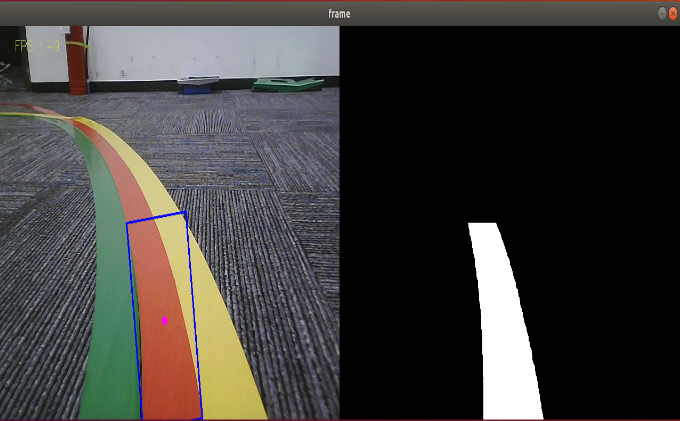
image-20210908183504399

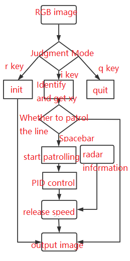
Keyboard key control:

【r】: Color selection mode, you can use the mouse to select the area of the color to be recognized (cannot exceed the area range).

【i】: Target detection mode. The color image on the left (Color) and the binary image on the right (Binary).

【q】: Exit the program.

【Spacebar】: Follow the track.

In the color selection mode, you can use the mouse to select the area of the color to be recognized (cannot exceed the area range), as shown in the figure below, release it to start recognition.

image-20210913105346512

5.2.3. Color calibration

<PI5 needs to open another terminal to enter the same docker container
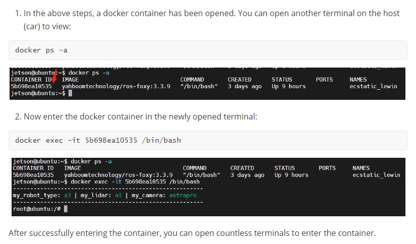
image-20240408144126098

Dynamic parameter debugging tool

xxxxxxxxxx
rosrun rqt_reconfigure rqt_reconfigure

Set the mode to [Target Detection Mode] and start the dynamic parameter debugging tool.
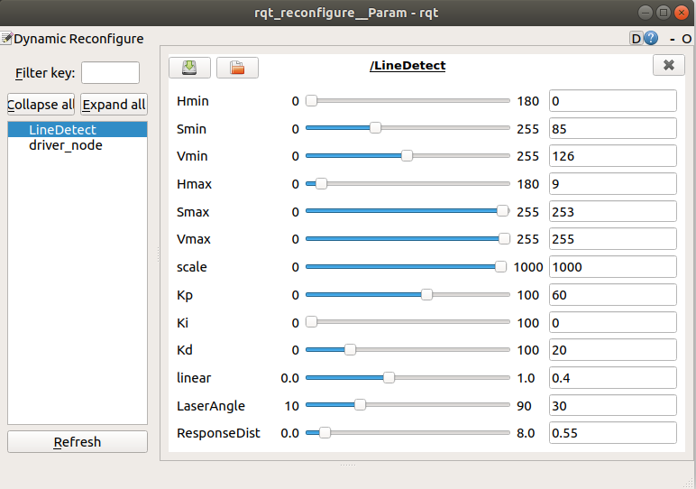
image-20220223143933038

Select the [LineDetect] node. Generally, you only need to adjust [Hmin], [Smin], [Vmin], and [Hmax]. These four parameters can be well identified. The slide bar is always in a dragging state and data will not be transferred to the system until it is released; you can also select a row and then slide the mouse wheel.

Parameter analysis:

[Kp], [Ki], [Kd]: PID control during car driving.

[scale]: PID scaling.

[linear]: Car running speed; range [0, 1.0], unit: meters; set as required.

[LaserAngle]: Lidar effective angle; range [0, 180], unit: degree; set as required.

[ResponseDist]: lidar response distance; range [0.15, 8.0], unit: meters; set as required.

  • Parameter modification

When the parameters are adjusted to the optimal state, the corresponding parameters are modified into the file, and no adjustment is required when using again.

According to the optimal parameters of the [rqt_reconfigure] debugging tool, enter the [scripts] folder of the [yahboomcar_linefollw] function package and modify the parameters corresponding to the [follow_line.py] file, as shown below

xxxxxxxxxx
class LineDetect:
     def __init__(self):
         rospy.on_shutdown(self.cancel)
         rospy.init_node("LineDetect", anonymous=False)
         ... ...
         self.scale = 1000
         self.FollowLinePID = (60, 0, 20)
         self.linear = 0.4
         self.LaserAngle = 30
         self.ResponseDist = 0.55
         self.PID_init()
         ... ...

[rqt_reconfigure] Modification of the initial value of the debugging tool

xxxxxxxxxx
gen.add("Hmin", int_t, 0, "Hmin in HSV", 0, 0, 180)
gen.add("Smin", int_t, 0, "Smin in HSV", 85, 0, 255)
gen.add("Vmin", int_t, 0, "Vmin in HSV", 126, 0, 255)
gen.add("Hmax", int_t, 0, "Hmax in HSV", 9, 0, 180)
gen.add("Smax", int_t, 0, "Smax in HSV", 253, 0, 255)
gen.add("Vmax", int_t, 0, "Vmax in HSV", 255, 0, 255)
gen.add("scale", int_t, 0, "scale", 1000, 0, 1000)
gen.add("Kp", int_t, 0, "Kp in PID", 60, 0, 100)
gen.add("Ki", int_t, 0, "Ki in PID", 0, 0, 100)
gen.add("Kd", int_t, 0, "Kd in PID", 20, 0, 100)
gen.add("linear", double_t, 0, "linear", 0.4, 0, 1.0)
gen.add("LaserAngle", int_t, 0, "LaserAngle", 30, 10, 90)
gen.add("ResponseDist", double_t, 0, "ResponseDist", 0.55, 0, 8)
exit(gen.generate(PACKAGE, "LineDetect", "LineDetectPID"))

Enter the [cfg] folder of the [yahboomcar_linefollw] function package and modify the initial values of the parameters corresponding to the [LineDetectPID.cfg] file. The color [HSV] adjustment parameters do not need to be modified. The system will automatically generate the [LineFollowHSV.text] file, which will be automatically read when the system starts.

xxxxxxxxxx
gen.add("Kp", int_t, 0, "Kp in PID", 60, 0, 100)

Take the above article as an example to analyze

ParametersAnalysisCorresponding parameters
nameThe name of the parameter"Kp"
typeparameter data typeint_t
levela bitmask passed to the callback0
descriptionA description parameter"Kp in PID"
defaultInitial value for node startup60
minparameter minimum value0
maxparameter maximum value10.0

Note: After modification, you must recompile and update the environment to be effective.

xxxxxxxxxx
cd ~/yahboomcar_ws
catkin_make
source devel/setup.bash

5.2.4. Tracking driving

After identifying that there is no problem, click the [space bar] on the keyboard to execute the tracking program.

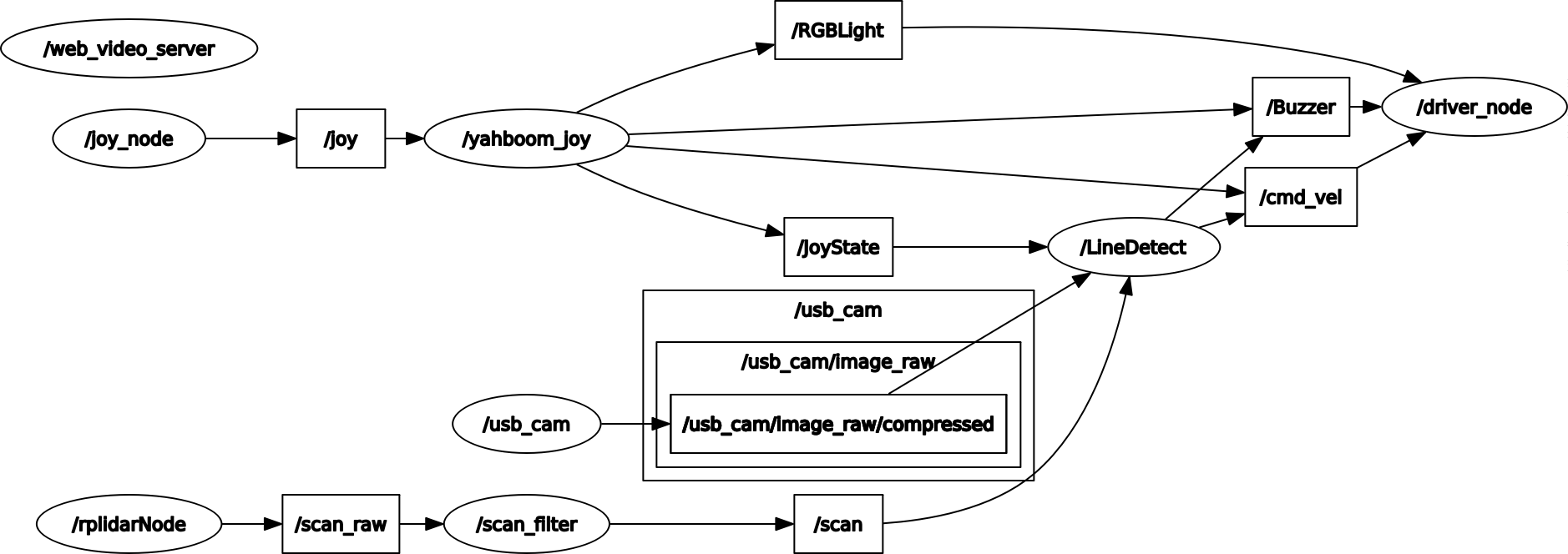
Node view

xxxxxxxxxx
rqt_graph

line_rosgraph


【LineDetect】Node analysis

image-20220223172848266

  • Subscribe to lidar

  • Subscribe to images

  • Subscription handle

  • Publish speed information

  • Post buzzer messages

Astra Object Tracking
Pure visual 2D mapping and navigation

COMPANY

  • About us
  • Team Style
  • Blog

LEARNING & EXPLORATION

  • Tutorials
  • Edge AI hardware
  • Educational robots
  • Embedded intelligent hardware

WHERE TO BUY

  • Yahboom Online Store
  • Amazon
  • Alibaba
  • AliExpress
  • Mercado

TECHNOLOGY SUPPORT

  • Email: support@yahboom.com

BE A DISTRIBUTOR

  • Email: sales@yahboom.com
QR Code

Copyright © 2017-2026 Yahboom. All Rights Reserved.

EN/中文