Welcome to ROSMASTER X3 repository
4. KCF object tracking
4、KCF object tracking
1、Program Function Description
After the program starts, select the object to be tracked with the mouse, press the Space bar, and the car enters the tracking mode. The car will maintain a distance of 1 meter from the tracked object and always ensure that the tracked object remains in the center of the screen.Press the R key to enter the selection mode, and press the Q key to exit the program. After the controller program starts, you can also pause/continue tracking by pressing the R2 button on the controller.
2、Code reference path
For the Raspberry Pi PI5 main control, you need to enter the docker container first, but the Orin main board does not need to enter.
the source code for this function is located at,
x~/yahboomcar_ros2_ws/yahboomcar_ws/src/yahboomcar_KCFTracker/src/KCF_Tracker.cpp
3、Program startup
3.1、start command
based on the actual vehicle model, the terminal inputs,
xxxxxxxxxx#Start the trolley chassisros2 run yahboomcar_bringup Mcnamu_driver_X3#Starting a depth camera, using astroprops as an exampleros2 launch astra_camera astro_pro_plus.launch.xml#Start handle noderos2 run yahboomcar_ctrl yahboom_joy_X3ros2 run joy joy_node#Launch KCF tracking programros2 run yahboomcar_KCFTracker KCF_Tracker_Node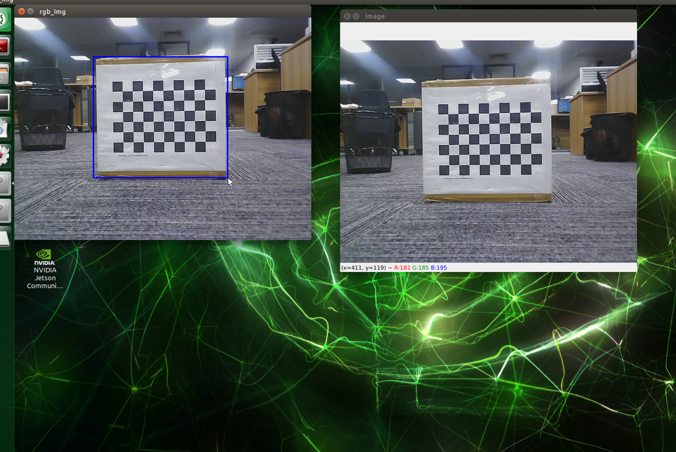
Use the mouse to box out the object to be tracked, and release to select the target. Then press the Space bar to start tracking and move the object slowly. The car will follow and keep 1m away from the object.
You can also use a dynamic parameter adjuster to debug parameters, Docker terminal input,
xxxxxxxxxxros2 run rqt_reconfigure rqt_reconfigure
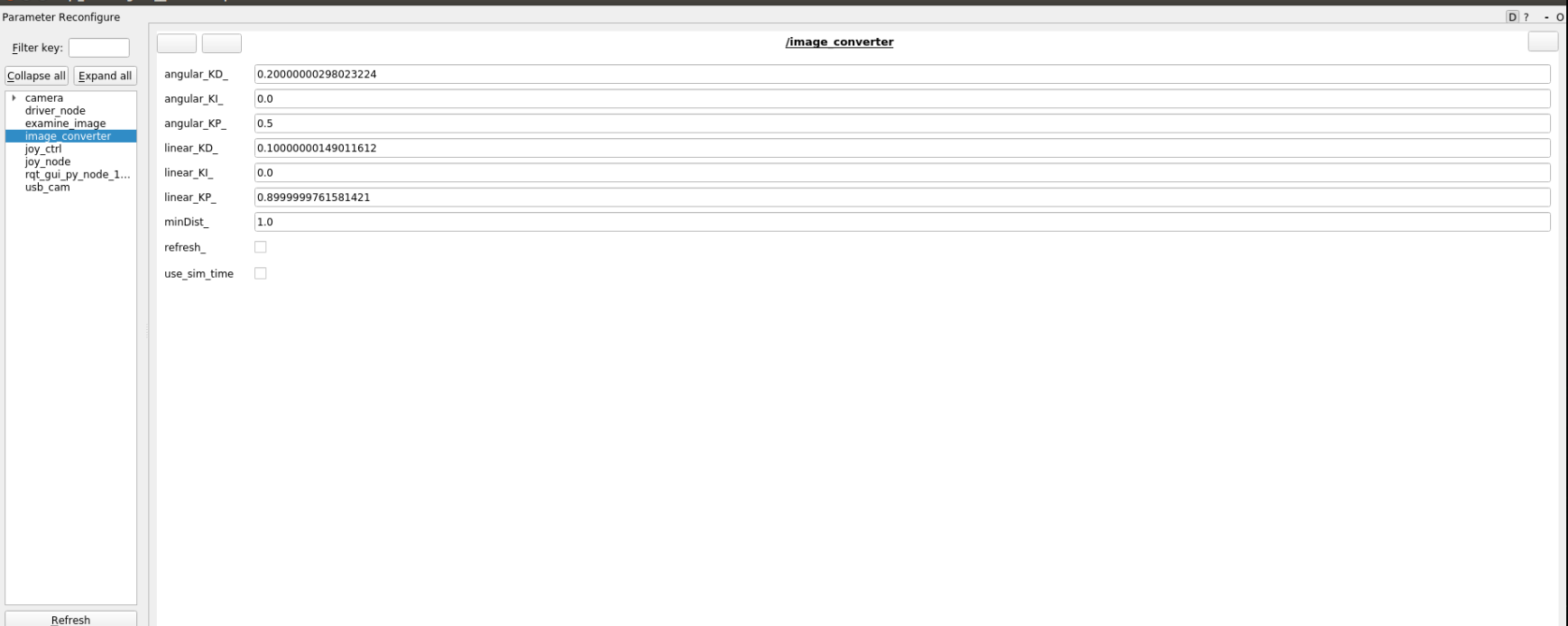
The adjustable parameters include the PID of the car's linear speed, angular speed, and tracking distance. After modifying the parameters, click "refresh" to refresh the data.
3.2、View node topic communication diagram
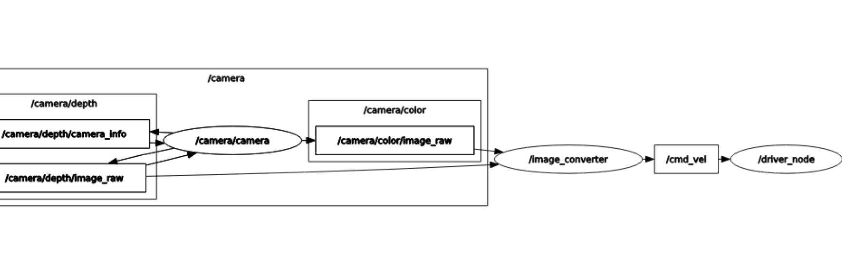
You can view topic communication between nodes using the following command,
xxxxxxxxxxros2 run rqt_graph rqt_graph
4、Core code
The principle of functional implementation is similar to color tracking, which calculates linear velocity and angular velocity based on the center coordinate of the target and the depth information fed by the depth camera, and then releases them to the chassis. Some of the code is included below,
x//This section is used to calculate the angular velocity by obtaining the center coordinate after selecting the objectif (bBeginKCF) { result = tracker.update(rgbimage); rectangle(rgbimage, result, Scalar(0, 255, 255), 1, 8); circle(rgbimage, Point(result.x + result.width / 2, result.y + result.height / 2), 3, Scalar(0, 0, 255),-1); } else rectangle(rgbimage, selectRect, Scalar(255, 0, 0), 2, 8, 0);
//This part calculates the center_ x. The value of distance, used to calculate speedint center_x = (int)(result.x + result.width / 2);int num_depth_points = 5;for (int i = 0; i < 5; i++) { if (dist_val[i] > 0.4 && dist_val[i] < 10.0) distance += dist_val[i]; else num_depth_points--;}distance /= num_depth_points;
//Calculate linear velocity and angular velocityif (num_depth_points != 0) { std::cout<<"minDist: "<<minDist<<std::endl; if (abs(distance - this->minDist) < 0.1) linear_speed = 0; else linear_speed = -linear_PID->compute(this->minDist, distance);//-linear_PID->compute(minDist, distance)}rotation_speed = angular_PID->compute(320 / 100.0, center_x / 100.0);//angular_PID->compute(320 / 100.0, center_x / 100.0)