Welcome to Raspbot repository
5.10 IR control test
1. In order to avoid the interference of sunlight on the infrared sensor, we must carry out the experiment indoors.
2. During remote control, the infrared remote control needs to be aimed at the infrared receiver on the expansion board.
1. Learning target
In this course, we mainly learn how to make the infrared receiver on the car read the value of the infrared remote control.
2. Principle of experimental
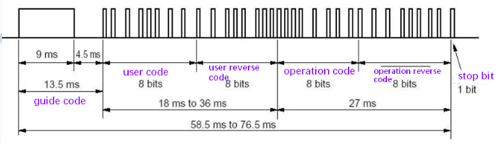
Infrared sending and receiving codes are divided into: guide code, user code, user reverse code, operation code(data code), operation reverse code(data reverse code).
Below we will introduce these kinds of encoded waveform:
For the part of infrared transmission, the infrared remote control we provided has been set up. Therefore, we do not explain the knowledge about infrared transmission here, but mainly explain some points of infrared reception.
We mainly use the NCE protocol:
The protocol stipulates that the lower bits are transmitted first.
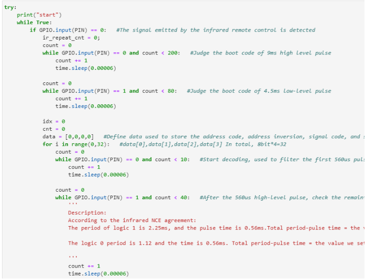
A string of information first sends a 9ms high pulse of AGC (Automatic Gain Control) . Then, send a 4.5ms low level. Next, send four-byte address code and a command code. These four bytes are : Address code, address reverse code; command code; command reverse code.
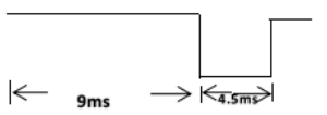
1)Guide code:The guide code defined by the uPD6121G of the NEC protocol is 9ms high level+ 4.5ms low level, waveform as shown in the figure below:
2)User code and operation code: The user code and operation code defined by the uPD6121G of the NEC protocol is:
"Logic 0" : 0.56ms high level + 0.565ms low level;
"Logic1" : 0.56ms high level + 1.685ms low level;
Waveform as shown below :
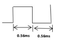
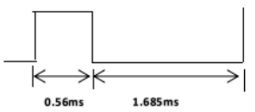
Logic 0 --waveform Logic 1--waveform
The wave output after passing through the infrared receiver, as shown below:
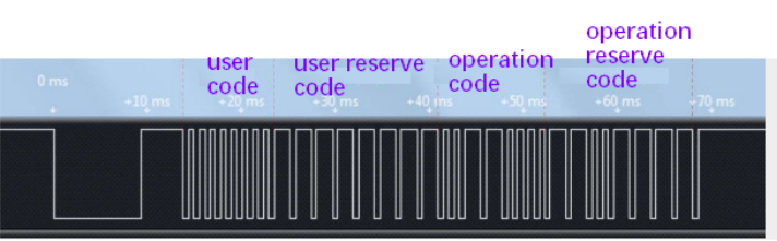
If you keep pressing that button, a series of messages can only be sent once. If you keep pressing, the repeating code is sent with a period of 110ms. Waveform as shown below.

The repeat code is composed of a high AGC level of 9ms, a low level of 2.25ms, and a high level of 560us, until the key is released. Waveform as shown below:
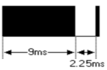
The process of infrared receiving and controlling the car is as follows:
1) Generate a falling edge, enter the interrupt function of external interrupt 0, and check whether the IO port is still low level after delay time. If it is low level, wait for the low level of 9ms to pass. Wait for the 9ms low level to pass, and then wait for the 4.5ms high level to pass.
2) Start receiving the 4 sets of data transmitted, wait for the low level of 560us to pass, and detect the duration of the high level. If it exceeds 1.12ms, it is high level (the duration of the high level is 1.69ms, the low level Duration is 5.65ms.)
3) Detect whether the received data is the same as the data reverse code (operation reverse code), and wait for the same data. If it is the same, it is proved that the corresponding data sent by the infrared remote control is received. Then, the car moves according to the function set in the program.
3. Coding method
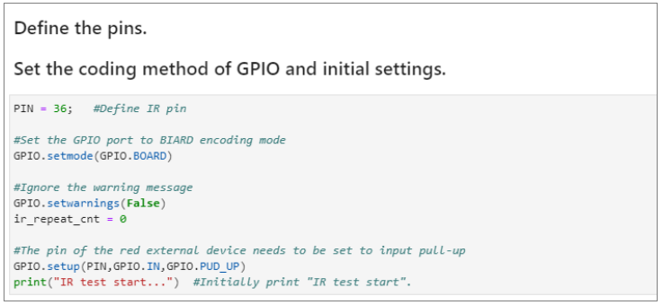
In this course, we use BOARD coding method.
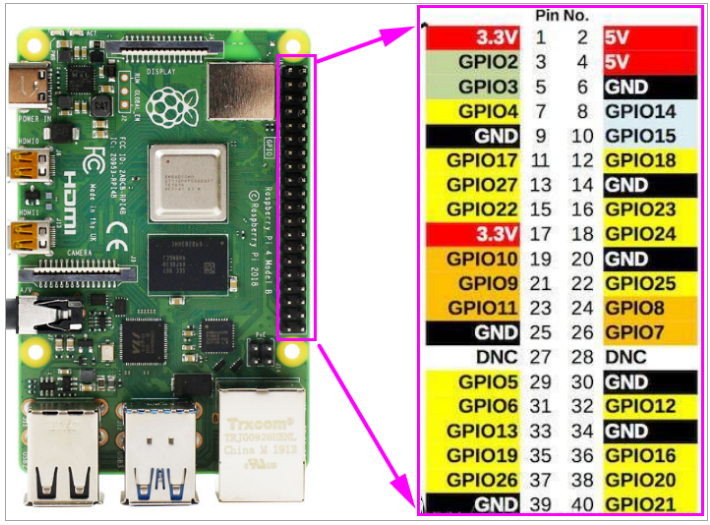
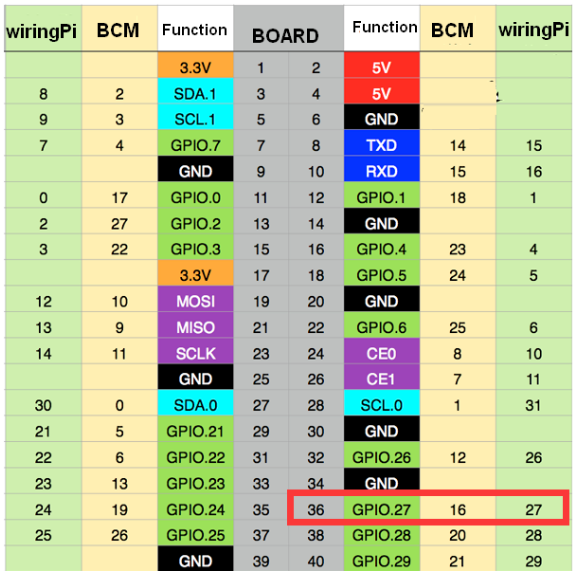
According to the hardware interface manual, we know that the Raspberry Pi pin that the infrared receiving sensor is connected to is 36.
The pin comparison table of Raspberry Pi is shown below.
4. About code
Path: /home/pi/Yahboom_project/Raspbot/2.Hardware Control course/09.IR control test/IR control test.ipynb
1) Import time and GPIO library
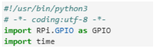
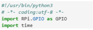
2) Set the GPIO coding mode, set the GPIO of the infrared receiver to the pull-up input mode
3) According to the NCE protocol, it receives the pilot code, address code, address inversion, signal code, and signal inversion of the infrared signal.
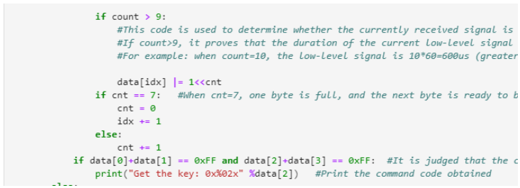
4) Determine whether the button is released according to the repeated signal

5. Running code
Click the button shown in the figure below to run the program on the Jupyter Lab interface

6. Experimental phenomena
When we press the infrared remote control, the code value of the button will be printed out.