Welcome to ESP32 WiFi Camera Lite repository
6. Microbit drives the servo gimbal
Microbit remote control servo gimbal
1. Experimental preparation
Module World expansion board
microbit
wifi camera
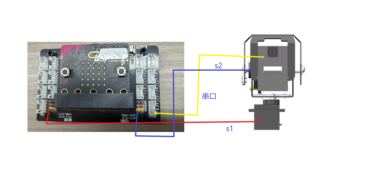
2. Experimental wiring
Note: Due to insufficient voltage, esp32 camera requires additional power supply via type-c data cable
| Expansion board | esp32 camera |
|---|---|
| P16 | RX |
| P15 | TX |
| GND | GND |
| 5V | 5V |
Wiring instructions:
| superkit | wifi camera |
|---|---|
| Servo interface P1 | Vertical servo |
| Servo interface P2 | Horizontal servo |
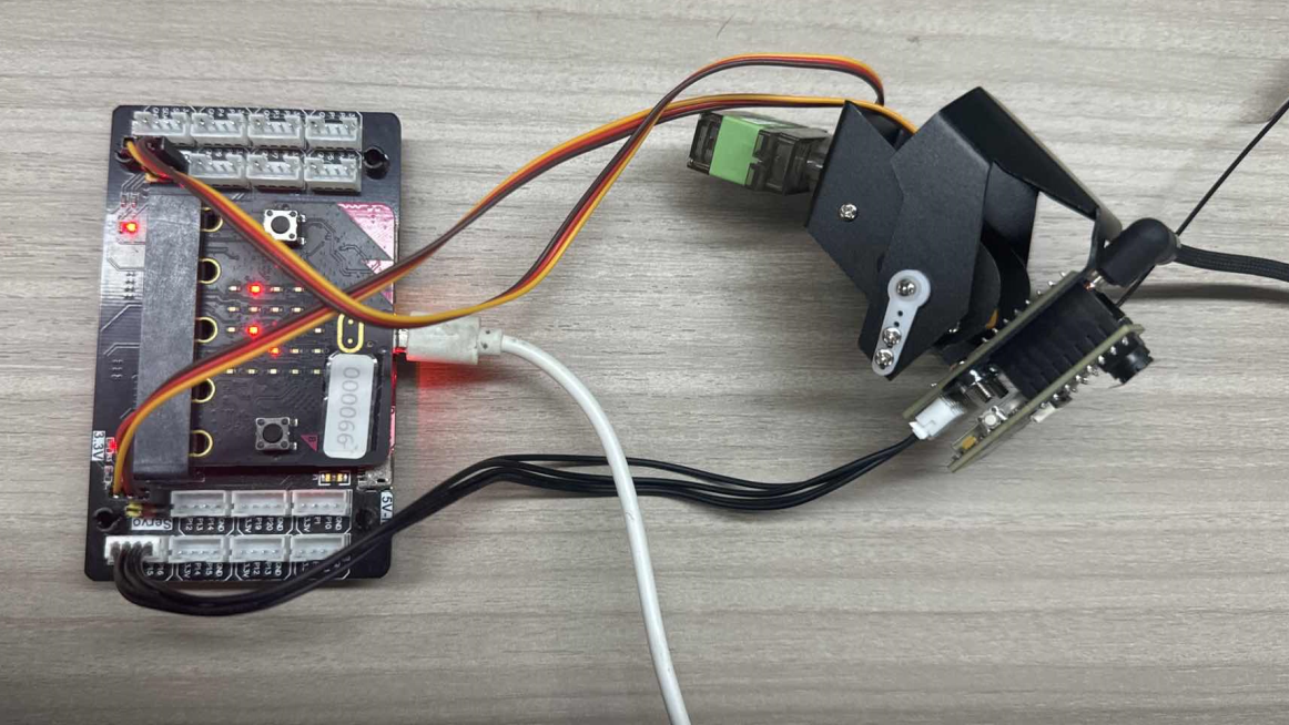
Physical wiring diagram:
3. Import and briefly explain the building blocks of microbit
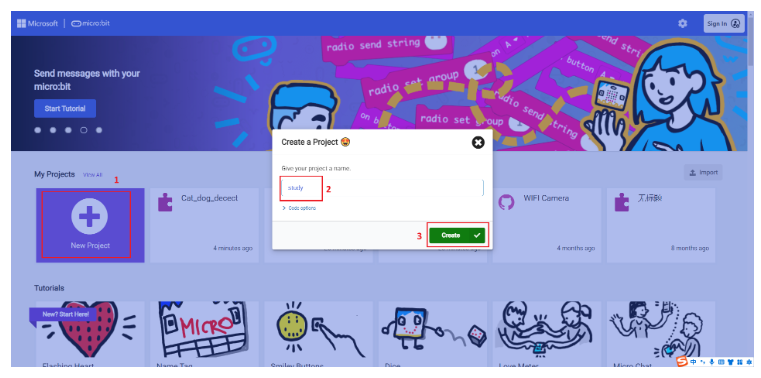
3.1 Open the programming website
https://makecode.microbit.org/#
3.2 Create a new project
3.3 Add the camera block
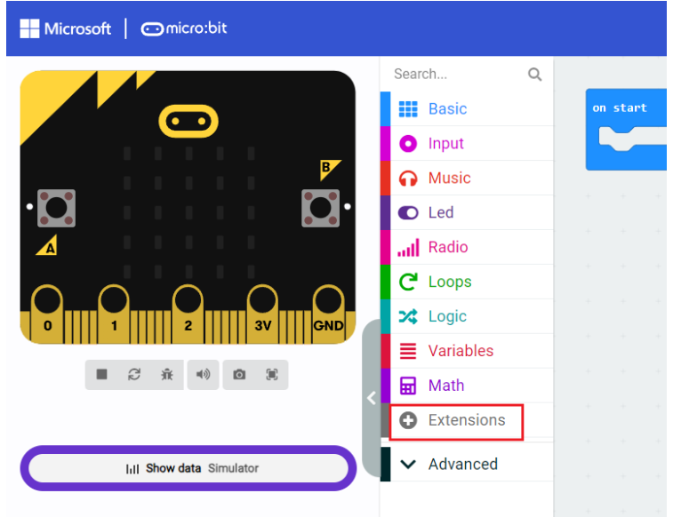
Block URL:
https://github.com/YahboomTechnology/ESP32-wifi-Microbit.git
Servo block URL:
https://github.com/lzty634158/yahboom_mbit
3.4 Introduction to the main blocks
After successfully introducing the above blocks, the result will be displayed as shown in the figure below
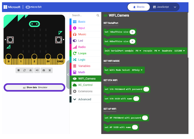
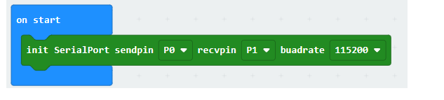
Serial port initialization block This is used to define the pins for serial communication, and communicate with the wifi camera. The baud rate is 115200 by default and cannot be changed
Set the size of the serial port receiving buffer This block is used to define the size of a packet of data that can be accepted for transparent transmission, for example
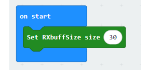
This defines that the maximum size of a packet is 30 characters. Exceeding this will result in incomplete data reception. This value cannot be less than 25, otherwise the IP information will also be incomplete
Drive servo pin, followed by adjustable angle.

You can know the functions of other building blocks by looking at their names. For how to use them, you can look at the source code provided in this tutorial. This tutorial will not explain how to open the source code provided in the tutorial
Open the URL https://makecode.microbit.org/# in the browser
Then drag the hex file provided in this experiment into the browser that opens the URL, and it will open automatically
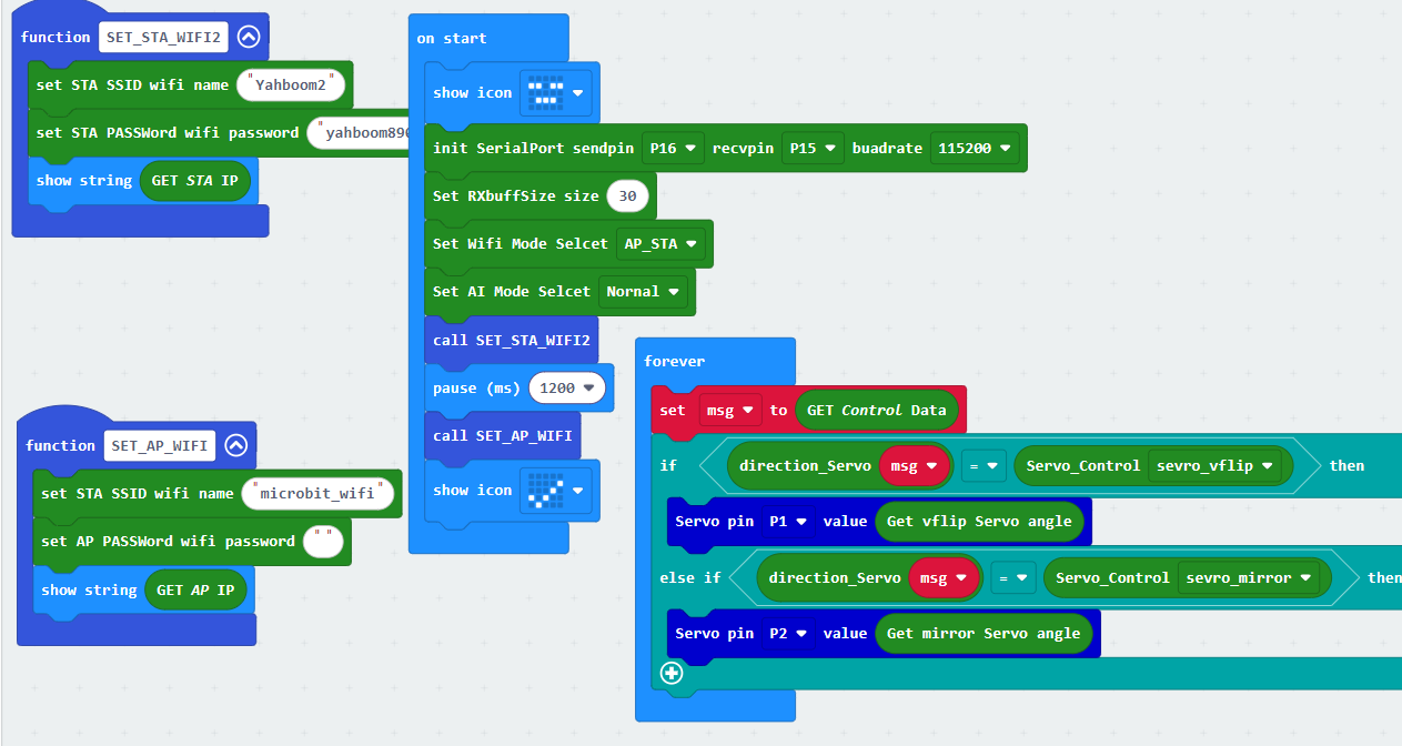
The program diagram of the source code of this project
4. Experimental operation and experimental results
From the source code, we can see that microbit will first initialize the serial port and then configure the working mode of the wifi camera.
Then configure the Wif to be connected according to the settings
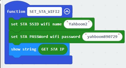
The Wifi here needs to be changed to a Wifi that can be connected
If the connection is successful, microbit will display sta_ip:192.168.x.x address. If the connection is unsuccessful, it will display sta_ip:null. If it is only configured as the self-heating point mode, it is also impossible to find the IP address of sta_ip, and it will also display sta_ip:null result
This is the configuration of the self-heating point
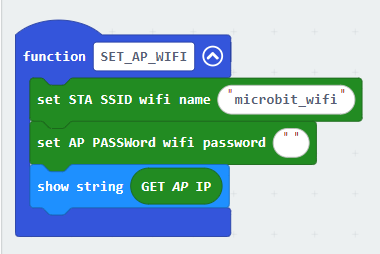
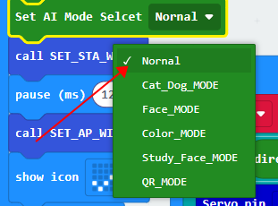
If the configuration is successful, the mobile phone can receive the microbit_wifi wifi hotspot, and can connect to this wifi by configuring a password or without a password, and microbit will display the ip of "ap_ip:192.168.4.1". If this name cannot be found, check whether it is configured to connect to wifi mode only (the mode in the figure below), and microbit will display the information of "ap_ip:null"
Set to normal mode
Download the program, you can directly pull the corresponding hex file of the source code to the recognized microbit drive letter. You can also click to download on the web
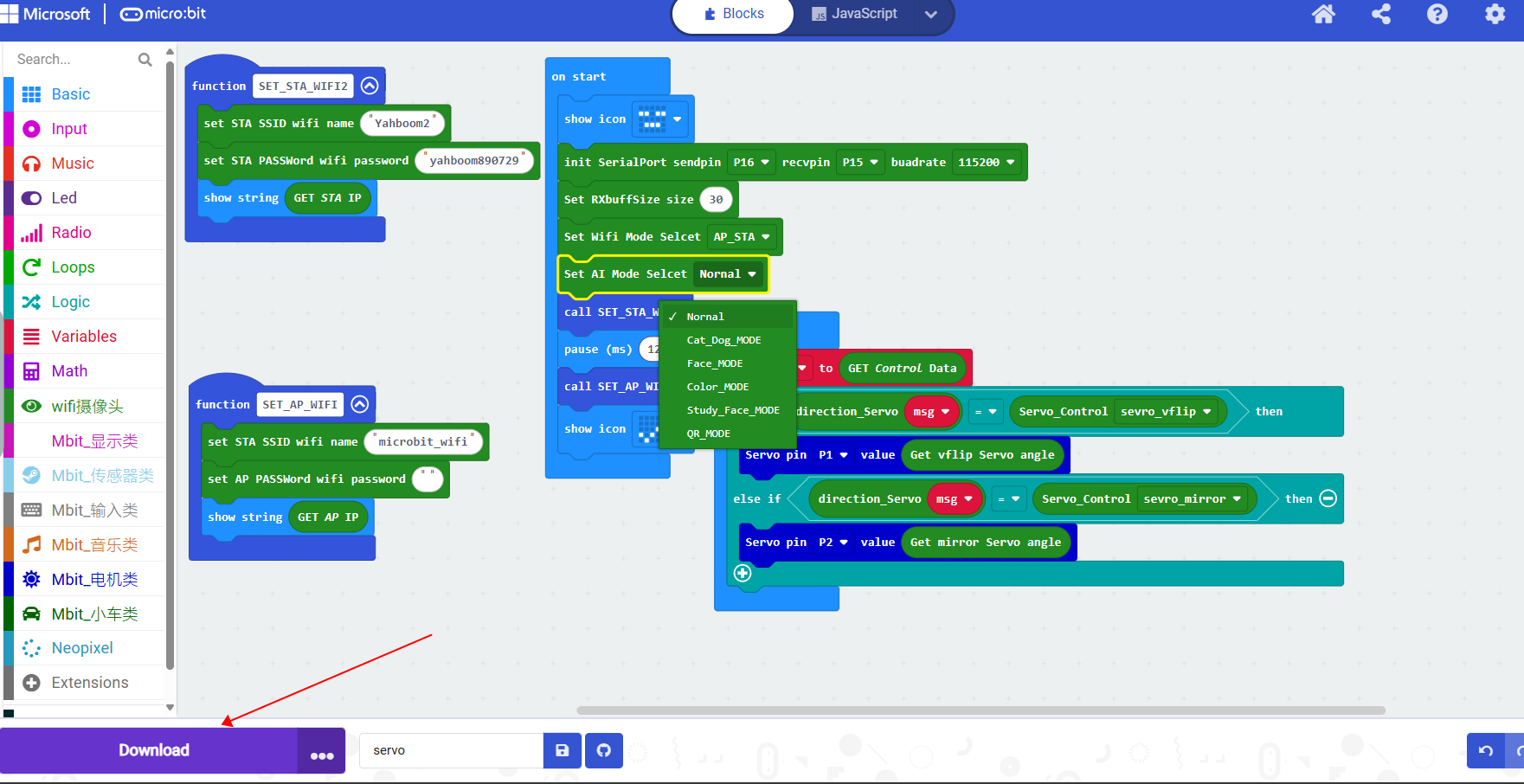
After downloading, microbit will display the sta_IP address and ap_ip address. Finally, a √ symbol is displayed, which means the download is successful.
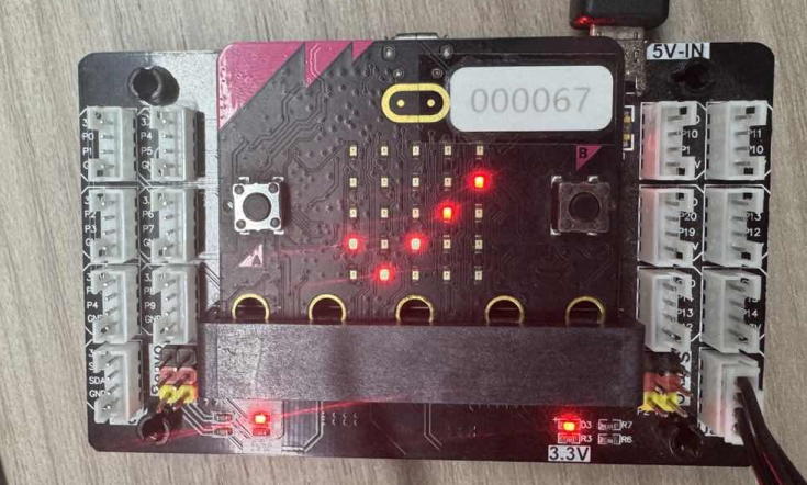
Use the app to control the movement of the car. After installing the "ESP32Cam" app, open it.
On the login page, set it according to the IP obtained by the serial port assistant. If the IP obtained by the serial port assistant is "192.168.2.50", then configure it as follows
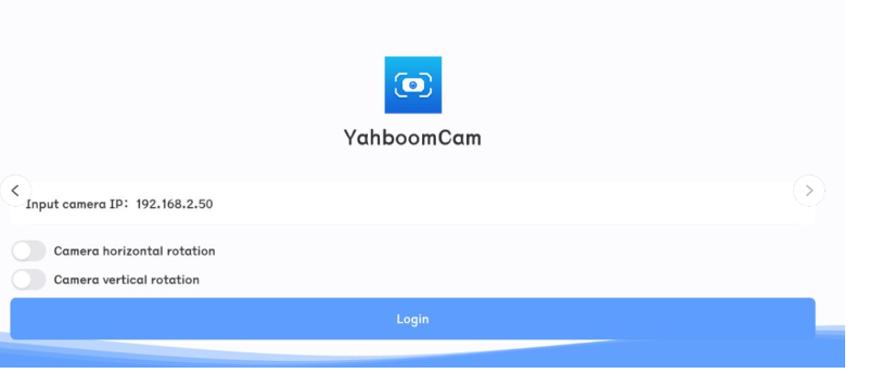
Then click login directly
(Optional) If you want to connect to the hotspot of the wifi camera, the IP address must be set to 192.168.4.1, as shown in the figure
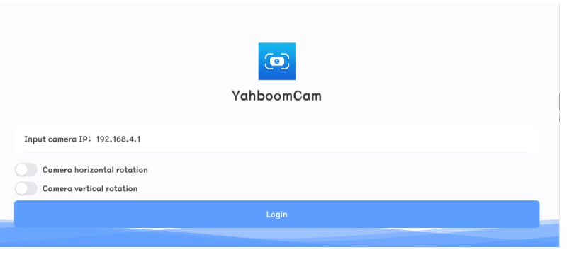
When the IP address is configured correctly and successfully connected, you can control the servo gimbal through the page of the app console
Horizontal screen
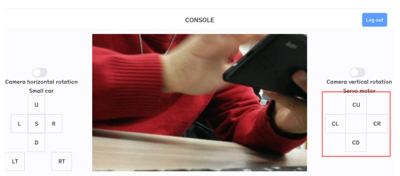
Note: Every time you restart the app, you need to click the exit button in the upper right corner, then exit and reconfigure the IP address information before logging in