Welcome to 520 Motor repository
04.Position PID
Position PID
Position PIDPosition discrete PID formulaDifference between position/incremental PIDCode implementationSoftware codeExperimental phenomenon
Position PID control compares the difference between the actual output and the expected output, and adjusts the control output according to the size of the error.
Position discrete PID formula
Uk: output
e(k): current deviation
e(k-1): last deviation
Kp: proportional term parameter
Ki: integral term parameter
Kd: differential term parameter
Difference between position/incremental PID
Position PID
Position PID calculates the current deviation value (difference between target value and actual value), integral value (sum of past errors) and differential value (error change rate), and then adds these three parts to obtain the PID output.
Incremental PID
Incremental PID obtains the PID output increment by calculating the change in the difference between the current error and the previous error.
xPositional PID requires accumulation of integral terms, which is suitable for situations where the system has high requirements for steady-state error.Incremental PID does not require accumulation of integral terms, which is suitable for situations where the system has high requirements for response speed.
Code implementation
Positional PID is position closed-loop control. Position closed-loop control is to measure the position information of the motor based on the pulse accumulation of the encoder, and compare it with the target value to obtain a deviation. Then we control the deviation proportionally, integrally, and differentially to make the deviation approach 0.
xxxxxxxxxxint Position_PID (int position,int target){static float error,Pwm,Integral_error,Last_error;error=target-position; // Calculate deviationIntegral_error+=error; // Calculate the integral of the deviationif(Integral_error>1000)Integral_error=1000;if(Integral_error<-1000)Integral_error=-1000;Pwm=Position_KP*error+Position_KI*Integral_error+Position_KD*(error-Last_error); // Position PID controllerLast_error=error; // Save the last deviationreturn Pwm; // Incremental output}
Software code
Since the relevant peripheral driver tutorial has been introduced before, it will not be introduced here!
xxxxxxxxxxSource code path of product supporting materials: Attachment → Source code summary → 3.PID_Course → 04.Position_PID
Experimental phenomenon
The Position_PID.hex file generated by the project compilation is located in the OBJ folder of the Position_PID project. Find the Position_PID.hex file corresponding to the project and use the FlyMcu software to download the program.
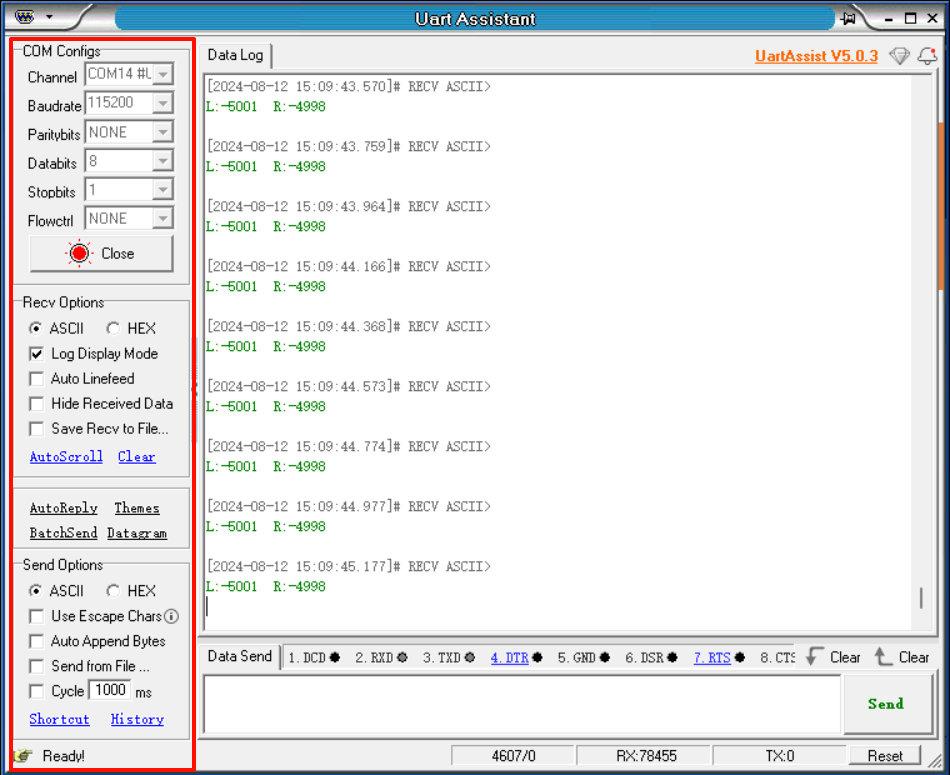
After the program is successfully downloaded: the motor will rotate to the vicinity of the preset encoder count value, the serial port will print the button status and the motor encoder value (corresponding to the distance the motor rotates), and the button can switch the LED status and control the motor to run to the set pulse position and stop.
Note: Since each motor is different, the value printed by the serial port may be a little different from the value set by the program; we can modify the Kp, Ki, and Kd parameters in the program to make the encoding value as close to the value set by the program as possible.
xxxxxxxxxxWhen using the serial port debugging assistant, you need to pay attention to the serial port settings. If the settings are wrong, the phenomenon may be inconsistent.