Welcome to 520 Motor repository
06.Cascade PID
Cascade PID
Cascade PIDCascade PIDSingle-stage/cascade differenceSingle-stage PIDCascade PIDCode implementationSoftware codeExperimental phenomenon
Tutorial demonstrates cascade PID control of motor.
Cascade PID
Cascade PID: The output of the previous PID controller is used as the input of the next PID controller.
In cascade PID control, the speed loop is used as the inner loop and the position loop is used as the outer loop: the output of the position PID is used as the input of the speed PID, that is, the output of the position PID is used as the target value of the speed PID for control.
Example: Control the motor to reach a specified distance at a specified speed.
Single-stage/cascade difference
Single-stage PID
Position PID can make the motor run a specified number of turns, but the speed control during the movement is relatively poor.
Incremental PID can make the motor run at a specified speed, but does not directly control the position or angle of the motor.
The specified number of turns and speed can be converted through motor parameters and encoder count values
Cascade PID
Position PID can control the distance/number of turns of the motor, and incremental PID can control the speed of the motor.
PID inner loop: incremental PID
PID outer loop: position PID
Code implementation
The output of position PID is used as the input of speed PID, that is, the output of position PID is used as the target value of speed PID for control
xvoid TIM6_IRQHandler(void){if (TIM_GetITStatus(TIM6, TIM_IT_Update) != RESET) //Check whether TIM update interrupt occurs{TIM_ClearITPendingBit(TIM6, TIM_IT_Update); //Clear TIMx update interrupt flagEncoder_Left = Read_Encoder(MOTOR_ID_ML);Encoder_Right = -Read_Encoder(MOTOR_ID_MR);Position_L +=Encoder_Left;Position_R +=Encoder_Right;Position_Motor_L = Position_PID(Position_L,Target_Position);Position_Motor_R = Position_PID(Position_R,Target_Position); motor_L = Incremental_PI(Encoder_Left,Position_Motor_L); motor_R = Incremental_PI(Encoder_Right,Position_Motor_R); motor_L = PWM_Ignore(motor_L); motor_R = PWM_Ignore(motor_R); motor_L = PWM_Limit(motor_L, 2500,-2500); motor_R = PWM_Limit(motor_R,2500,-2500); Set_Pwm(motor_L,motor_R); } } int Position_PID (int position,int target) { static float error,Pwm,Integral_error,Last_error; error=target-position; //Calculate deviation Integral_error+=error; //Calculate the integral of the deviationIntegral_error=PWM_Limit(Integral_error,Target_Velocity,-Target_Velocity); //Integral limitPwm=Position_KP*error+Position_KI*Integral_error+Position_KD*(error-Last_error); //Position PID controllerLast_error=error; //Save the last deviationPwm=PWM_Limit(Pwm,Target_Velocity,-Target_Velocity); //Position to incremental output limitreturn Pwm; //Incremental output}int Incremental_PI (int Encoder,int Target){static float error,Pwm,Last_error,Last_last_error;error=Target-Encoder; //Calculate the deviationPwm+=Incremental_KP*(error-Last_error)+Incremental_KI*error +Incremental_KD*(error-2*Last_error+Last_last_error); //Incremental PID controllerLast_error=error; //Save the last deviationLast_last_error = Last_error; //Save the last deviationreturn Pwm; //Incremental output}
Software code
Since the relevant peripheral driver tutorial has been introduced before, it will not be introduced here!
xxxxxxxxxxProduct supporting data source code path: Attachment → Source code summary → 3.PID_Course → 06.Contact_PID
Experimental phenomenon
The Contact_PID.hex file generated by the project compilation is located in the OBJ folder of the Contact_PID project. Find the Contact_PID.hex file corresponding to the project and use the FlyMcu software to download the program into it.
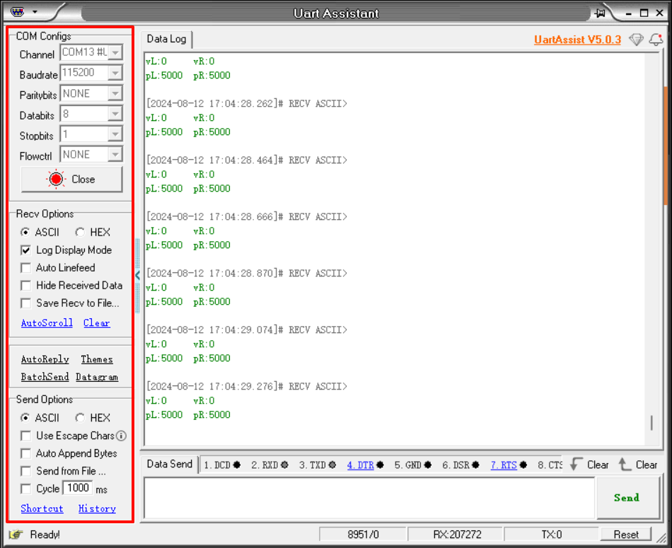
After the program is downloaded successfully: the motor will rotate to the preset encoder count value, the serial port will print the button status and motor speed and encoder value (corresponding to the distance the motor rotates), the button can switch the LED status and control the motor to run to the set pulse position and stop.
Note: Since each motor is different, the value printed by the serial port may be slightly different from the value set by the program; we can modify the Kp, Ki, Kd parameters in the program to make the encoding value as close to the value set by the program as possible.