Welcome to 520 Motor repository
Robot car LQR control
Balance car LQR high-level control
Balance car LQR high-level controlLQRLQR-Linear (Linear Model)LQR-Quadratic (Quadratic Cost Function)LQR-RegulatorLQR advantages and disadvantagesLQR and PIDLQR implementation ideas1. Establish a mathematical model of the balance car2. Design state space expressions3. Design objective function4. Design/implement LQR controllerDesign LQR controllerImplement LQR controller5. Simulation verification6. Practical applicationProgram running resultsCode Implementation
LQR (Linear Quadratic Regulator) is a commonly used high-order control method that can help the balancing car achieve stable movement.
LQR
LQR (Linear Quadratic Regulator) is a classic linear quadratic regulator used to design the optimal state feedback controller for continuous-time linear systems.
The performance of the system is optimized by minimizing a cost function, while considering the state and control input of the system.
LQR-Linear (Linear Model)
LQR-Linear refers to the use of the LQR algorithm for control design when the state space model of the system is linear.
The LQR-Linear algorithm can be used to calculate the optimal state feedback gain matrix K, and K can be adjusted to achieve stable control of the tilt angle and speed.
LQR-Quadratic (Quadratic Cost Function)
LQR-Quadratic refers to the use of a quadratic cost function to define the objective function, and the controller design is optimized by the LQR-Quadratic algorithm.
xxxxxxxxxxThe balance car can be adjusted to minimize the tilt angle deviation. We can add these factors to the quadratic cost function and use the LQR-Quadratic algorithm to design the corresponding optimal controller.
LQR-Regulator
LQR-Regulator can be used to adjust the state feedback matrix Q and the input feedback matrix R to achieve the regulation and stability of the system state.
xxxxxxxxxxThe response speed or stability of the balance car under different working conditions can be adjusted. The weight relationship between the controller's system state error and input power can be changed by adjusting the Q and R matrices, thereby achieving different regulation effects.
LQR advantages and disadvantages
| Advantages | Description |
|---|---|
| Stability | The LQR algorithm can design a stable closed-loop system so that the system can quickly restore balance when subjected to external disturbances |
| Performance optimization | By adjusting the state feedback matrix Q and the input feedback matrix R, the system performance can be optimized, such as fast response and error reduction. |
| Easy to implement | The LQR algorithm is a linear control method with simple calculation and easy implementation |
| Disadvantages | Description |
|---|---|
| High model requirements | The LQR algorithm requires an accurate system mathematical model for design. If the system model is inaccurate or has errors, it may lead to poor control effect |
| Low efficiency | In complex systems, the LQR algorithm may require a lot of computing resources and time to solve the optimal controller gain matrix K, resulting in low computational efficiency |
| Poor robustness | The LQR algorithm is sensitive to parameter changes and external interference, and may show poor robustness when facing nonlinear, time-varying or uncertain systems |
LQR and PID
LQR (Linear Quadratic Regulator) and PID (Proportional-Integral-Derivative) are two commonly used control algorithms, which have some differences in design principles, adjustment methods and applicable scenarios.
| LQR | PID | |
|---|---|---|
| Design Principle | LQR is a linear quadratic regulator based on the state space model. It designs the optimal controller by minimizing the weighted square sum of the system state variables. | PID is a classic feedback control algorithm that calculates the control output based on the proportion, integration and differentiation of the error signal. |
| Regulation Method | LQR adjusts and stabilizes the system state by adjusting the state feedback matrix Q and the input feedback matrix R. The trade-off between system performance indicators can be balanced by the weight matrices Q and R. | PID affects the controller's response speed, stability and anti-interference ability to the error signal by adjusting the proportional gain Kp, integral time Ti and differentiation time Td. |
| Applicable Scenarios | QR is suitable for linear dynamic systems and is usually used for control problems that require optimization of specific performance indicators (such as minimizing energy consumption, trajectory tracking, etc.). | PID is widely used in various industrial fields for control problems that do not require high control accuracy or do not require complex optimization targets. |
| Performance | LQR has good performance | PID is relatively simple and easy to implement |
LQR implementation ideas
LQR control block diagram: full-state feedback control system
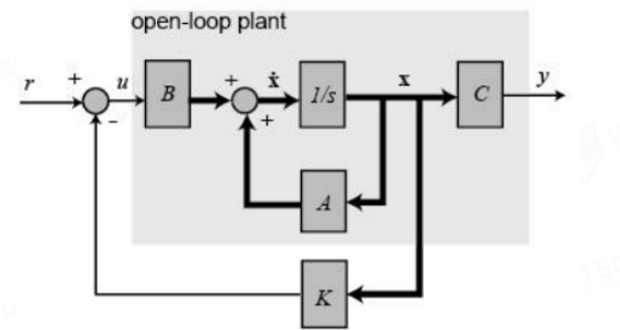
A, B, C: state space equations
K: gain matrix
1. Establish a mathematical model of the balance car
Establish a dynamic model of the balance car, including the motion equations of the balance car, state space expressions, etc.
xState space equations can describe the dynamic characteristics of the system, including state variables, input variables, system matrices, and output matrices, etc.
2. Design state space expressions
Convert the dynamic model of the balance car into a state space form, that is, a set of linear equations that describe the relationship between the system state and input.

①: State equation
②: Output equation
xxxxxxxxxxx is the system state vector, u is the control input vectorA, B, C, D are system parameter matrices
3. Design objective function
Based on the system performance indicators and requirements, design an objective function to evaluate the system performance.

③: Quadratic cost function
xxxxxxxxxxQ and R are the state feedback matrix and input feedback matrix respectively
4. Design/implement LQR controller
Design LQR controller
Based on the state space expression and objective function of the system, use the LQR algorithm to solve the optimal controller gain matrix K.
Determine the optimal state feedback matrix Q and input feedback matrix R by minimizing the objective function.
Implement LQR controller

- Solve the optimal gain matrix K: Use the LQR algorithm to solve the optimal state feedback matrix Q and input feedback matrix R when the cost function is minimized.
④: Riccati equation → Solve the optimal control problem of the linear system
⑤: Solve the gain matrix K of the LQR controller
- Controller output: Control input 𝑢=−𝐾𝑥
Apply the optimal controller gain matrix K to the balancing car system, and adjust the tilt angle and speed in real time to maintain balance.
xxxxxxxxxxThe controller will adjust the control input in real time according to the current system state to achieve the best performance of the system
5. Simulation verification
Matlab can directly calculate K using the lqr function
Use Matlab to verify the designed LQR high-order controller to check whether the system can work stably and meet the performance index requirements.
xxxxxxxxxxBy continuously optimizing parameters and adjusting strategies, the system can achieve better stability, robustness and performance
6. Practical application
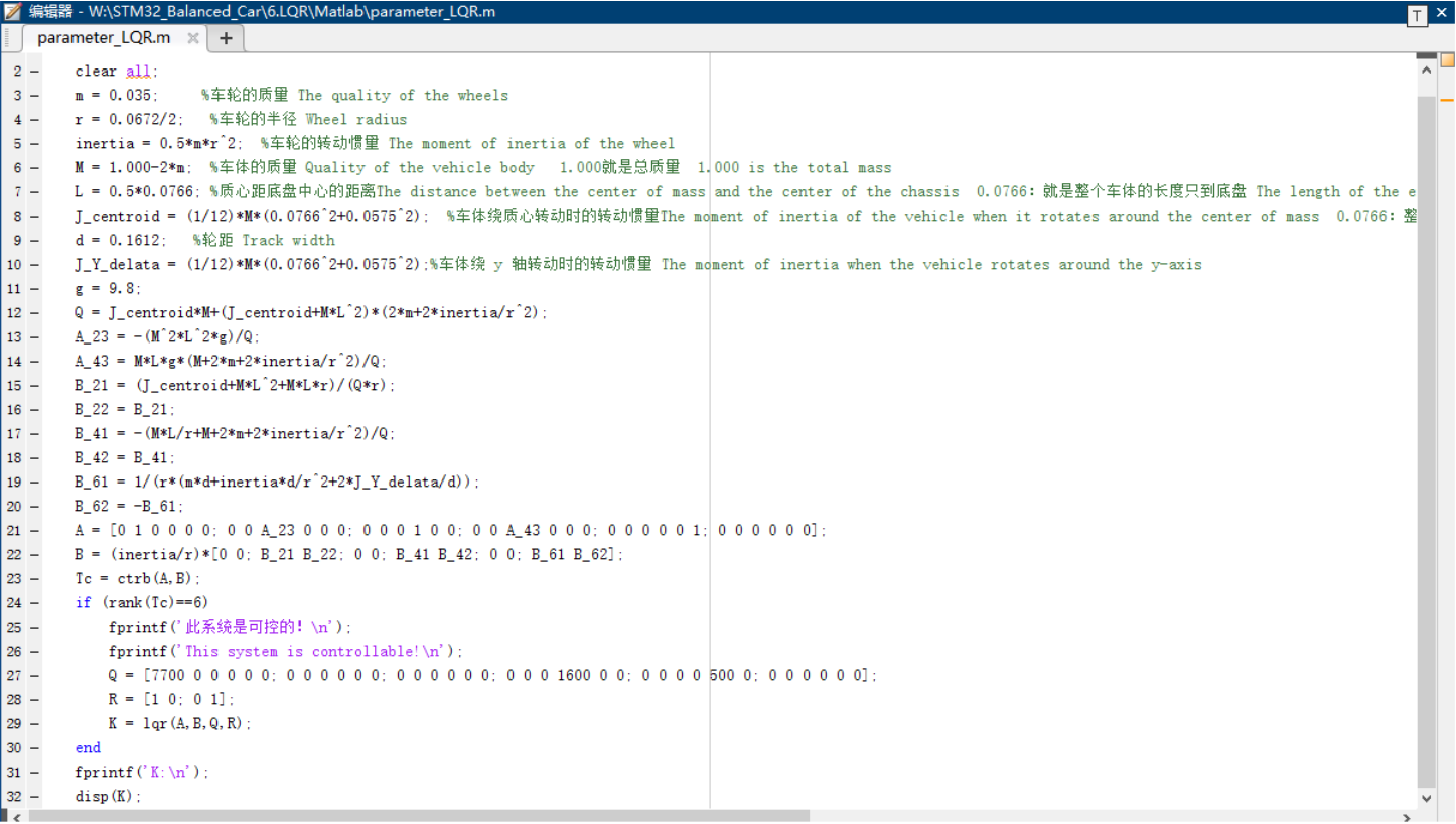
You need to use MATLAB to run the program parameter_LQR.m and modify the corresponding parameters in the program to adapt to your own car
xxxxxxxxxxProduct supporting materials source code path: Attachment → Source code summary → 6.LQR → Matlab
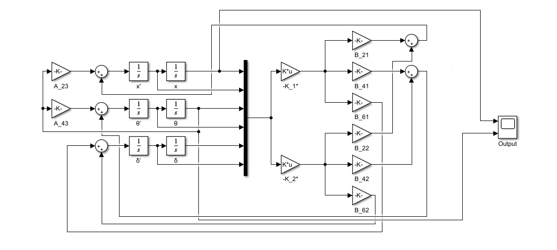
Use SIMULINK to simulate it:
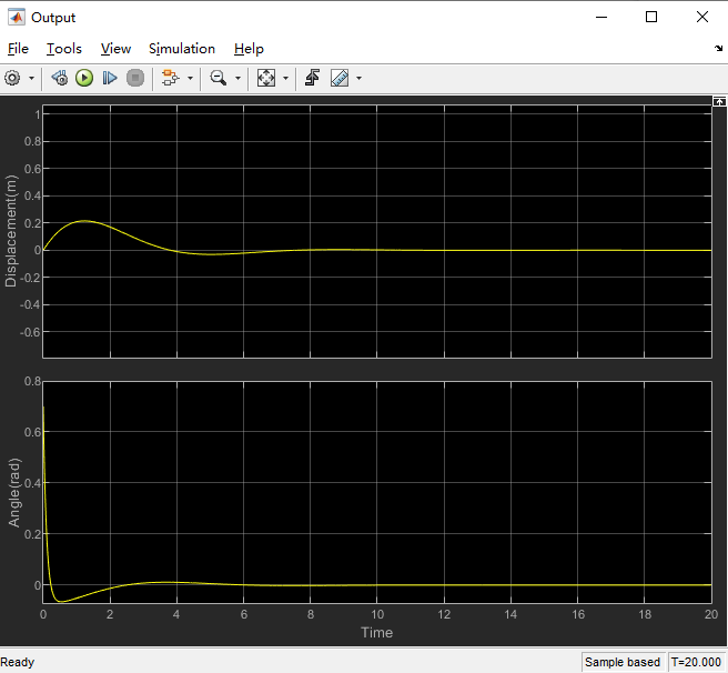
Simulation results:
Program running results
You can modify the parameters obtained by running the program to the corresponding code, and then fine-tune the parameters to achieve the best results!
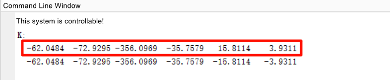
Code Implementation
When running this case code, the balancing car can only retain the standard package accessories, and other advanced accessories need to be removed; keep the balancing car vertical to the ground at 90° before starting.
xxxxxxxxxxProduct supporting materials source code path: Attachment → Source code summary → 6.LQR → STM32_code
Implementation code
xxxxxxxxxx//LQR状态反馈系数float K1= -62.1608, K2= -72.9295, K3=-356.0969, K4=-35.7579 , K5=15.8114, K6=15.8114;float K5OLD=15.8114, K6OLD=15.8114;L_accel=-(K1*x_pose+K2*(x_speed-Target_x_speed)+K3*(angle_x-Target_angle_x)+K4*gyro_x+K5*angle_z+K6*(gyro_z-Target_gyro_z));R_accel=-(K1*x_pose+K2*(x_speed-Target_x_speed)+K3*(angle_x-Target_angle_x)+K4*gyro_x-K5*angle_z-K6*(gyro_z-Target_gyro_z));