yahboom
HomeLearn
Solution
Blog
Online Store
About Us
EN/中文
520 Motor📖
1.About motor
  • About motor
2.ROS robot control board drive
  • 2.1 Control motor
  • 2.2 Timer captures encoder data
  • 2.3 PID control robot car
  • 2.4 Kinematic Analysis-Mecanum wheel structure
  • 2.5 Kinematic Analysis-Ackerman structure
  • 2.6 Kinematic Analysis-4WD structure
3.STM32 Self-balancing car tutorials
Get started quickly
  • 03.P, PI, PD controller theory
  • 01.Balancing car assembly
  • 02.Get started quicklyy
  • 03.Balance car interface description
  • 04.Common Problem Analysis
  • 05.Balance Car V2 Library Function Development Manual
Environment construction and development
  • 01.MDK-ARM installation
  • 02.STM32CubeIDE installation
  • 03.Common driver installation
  • 04.Download the program
  • 05.MDK-ARM project usage
  • 06.Program simulation
Robot car PID control course
  • 01.PID basic concept
  • 02.PID example analysis
  • 04.Position PID
  • 05.Incremental PID
  • 06.Cascade PID
  • 07.Balance principle of car
  • 08.Car upright control (PD)
  • 09.Car speed ​​control (PI)
  • 10.Car steering control (PD)
  • 11.Got angle and angular velocity (DMP algorithm)
  • 12.Got angle and angular velocity (Kalman filter algorithm)
  • 13.Got angle and angular velocity(Complementary filter algorithm)
Robot car basic course
  • 01.Car parameter adjustment
  • 02.Ultrasonic obstacle avoidance
  • 03.Ultrasonic follow
  • 04.Bluetooth remote control
  • 05.Load balance
Robot car LQR control
  • Robot car LQR control
Circuit design
  • 01.Overall circuit design
  • 02.STM32 minimum system
  • 03.Serial port circuit design
  • 04.Power circuit design
  • 05.MPU6050 Circuit Design
  • 06.Motor drive circuit design
Mathematical model
  • Balance car mathematical model
4.4-channel motor drive module
Introduction and Debug
  • 1.Introduction to 4-channel motor drive board
  • 2.Control command
  • 3.Motor introduction and usage
  • 4.PC host
IIC communication
  • For Arduino
  • For ESP32
  • For Jetson NANO
  • For MSPM0G3507
  • For MSPM0G3519new
  • For PICO2
  • For RDK X5
  • For RPi5
  • For STM32
USART communication
  • For Arduino
  • For ESP32
  • For Jetson NANO
  • For MSPM0G3507
  • For MSPM0G3519new
  • For PICO2
  • For RDK X5
  • For RPi5
  • For STM32
5.2-channel motor drive module
For MSPM0G3507
  • 1.AT8236 drive tutorials
  • 2.TB6612 drive tutorials
For MSPM0G3519
  • 1.AT8236 drive tutorialsnew
  • 2.TB6612 drive tutorialsnew
Download
  • Model File
  • Annex_ROS_robot_board
  • Annex_STM32_balancing_car
  • Annex_4channel_motor_drive
  • Annex_2channel_motor_drive
Download ZIP

Welcome to 520 Motor repository

03.Serial port circuit design

Serial port circuit design

Serial port circuit designSerial port circuit

Using the Type-C interface of the development board, you can download the program to the development board through the serial port burning software FlyMCU; in addition, you can also view the data through the serial port for debugging and other functions later.

Serial port circuit

The serial port chip used by the development board is CH340K, and its main function is to convert the USB interface to a serial port (UART) interface.

The computer and the development board cannot communicate directly through USB, and need to use USB to serial port for communication
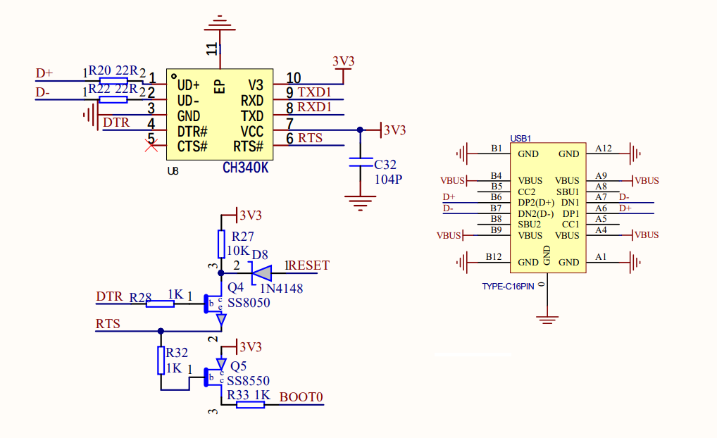
image-20240822163324561

STM32 minimum system
Power circuit design

COMPANY

  • About us
  • Team Style
  • Blog

LEARNING & EXPLORATION

  • Tutorials
  • Edge AI hardware
  • Educational robots
  • Embedded intelligent hardware

WHERE TO BUY

  • Yahboom Online Store
  • Amazon
  • Alibaba
  • AliExpress
  • Mercado

TECHNOLOGY SUPPORT

  • Email: support@yahboom.com

BE A DISTRIBUTOR

  • Email: sales@yahboom.com
QR Code

Copyright © 2017-2026 Yahboom. All Rights Reserved.

EN/中文