Welcome to IMU Sensor Module repository
For ESP32
ESP32-IIC Data Reading
This example uses the ESP32-WiFi image transmission module Lite version (Yabo), a Windows computer, several DuPont wires, an IMU attitude sensor, and a USB to TTL module.
1. Connecting Devices
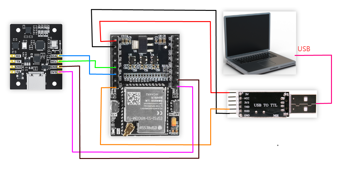
| IMU Attitude Sensor | ESP32-WiFi Image Transmission Module Lite (Yahboom) |
|---|---|
| SDA | SDA |
| SCL | SCL |
| GND | GND |
| 3V3 | 3V3 |
| USB to TTL | ESP32-WiFi Image Transmission Module Lite (Yahboom) |
|---|---|
| 5V | 5V |
| RXD | TX0 |
| GND | GND |
2. Key Code Analysis
Please refer to the source code in the documentation for specific code.
xxxxxxxxxx/** * @brief Read acceleration in g. * */int IMU_I2C_ReadAccelerometer(float out[3]){ uint8_t register_data[6]; if (read_register(IMU_FUNC_RAW_ACCEL, register_data, 6) != 0) { return -1; } if (out != NULL) { float ratio = 16.0f / 32767.0f; out[0] = to_int16(®ister_data[0]) * ratio; out[1] = to_int16(®ister_data[2]) * ratio; out[2] = to_int16(®ister_data[4]) * ratio; } return 0;}/** * @brief Read angular velocity in rad/s. * */int IMU_I2C_ReadGyroscope(float out[3]){ uint8_t register_data[6]; if (read_register(IMU_FUNC_RAW_GYRO, register_data, 6) != 0) { return -1; } if (out != NULL) { float ratio = (2000.0f / 32767.0f) * (3.1415926f / 180.0f); out[0] = to_int16(®ister_data[0]) * ratio; out[1] = to_int16(®ister_data[2]) * ratio; out[2] = to_int16(®ister_data[4]) * ratio; } return 0;}/** * @brief Read quaternion (w, x, y, z). * */int IMU_I2C_ReadQuaternion(float out[4]){ uint8_t register_data[16]; if (read_register(IMU_FUNC_QUAT, register_data, 16) != 0) { return -1; } if (out != NULL) { out[0] = to_float(®ister_data[0]); out[1] = to_float(®ister_data[4]); out[2] = to_float(®ister_data[8]); out[3] = to_float(®ister_data[12]); } return 0;}/** * @brief Read Euler angles (rad). * */int IMU_I2C_ReadEuler(float out[3]){ uint8_t register_data[12]; if (read_register(IMU_FUNC_EULER, register_data, 12) != 0) { return -1; } if (out != NULL) { const float RAD2DEG = 57.2957795f; out[0] = to_float(®ister_data[0]) * RAD2DEG; out[1] = to_float(®ister_data[4]) * RAD2DEG; out[2] = to_float(®ister_data[8]) * RAD2DEG; } return 0;}IMU_I2C_ReadAccelerometer(): Read acceleration data (unit g)
IMU_I2C_ReadGyroscope(): Reads angular velocity (in rad/s)
IMU_I2C_ReadQuaternion(): Reads quaternions
IMU_I2C_ReadEuler(): Reads Euler angles (in radians)
3. Reading IMU Data
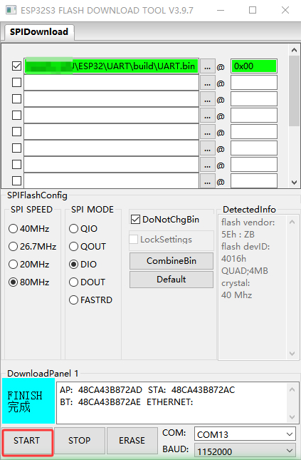
The bin file generated by the ESP32S3 programming example. Open the ESP32S3 programming tool, configure it as shown in the image below, and click the [START] button to download the bin file to the ESP32S3 development board.
After the program is downloaded to the ESP32, open the serial port assistant (configuration parameters are shown in the image below). You can see the IMU module data being continuously printed. When we change the attitude of the IMU module, the data will change.
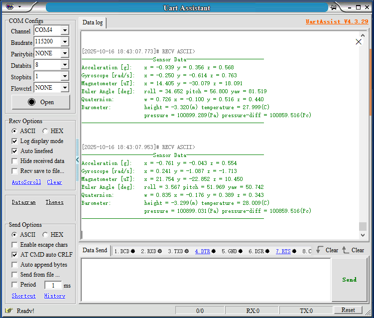
Note: The above data is from a 10-axis IMU, 6-axis data without magnetometer and barometer, and 9-axis data without barometer.