Welcome to IMU Sensor Module repository
1. Autonomous Driving Car
Autonomous Driving Car
1. Introduction
Please read the "Motor Introduction and Usage" section in the four-way motor driver board documentation first to understand the parameters, wiring methods, and power supply voltage of the motors you are currently using. This is to avoid burning out the motherboard or motors.
Usage Tips: In angle control tasks, the IMU may experience data drift after running multiple revolutions, so it may not run perfectly. You need to modify the value of the angle that the car should move forward in the code based on your actual measured offset.
2. Experiment Preparation
National Competition Chassis V2 Four-Wheel Drive Version, 4*L520 Motors, 12V Lithium Battery, Eight-Way Line Following Module, IMU Attitude Sensor (Yahboom), MSPM0 Robot Expansion Board (Optional), MSPM0G3507/MSPM0G3519 Core Board (Yahboom). The audio-visual cues required in Problem H are integrated into the MSPM0 robot expansion board (buzzer PB24) and the Yahboom version MSPM0G3507/MSPM0G3519 core board (LED PB2), respectively. Users not using the MSPM0 robot expansion board need to provide their own buzzer. The problem selection function button K1 (PA2) is located on the MSPM0 robot expansion board.
The relationship between the four motor interfaces and the robot is as follows:
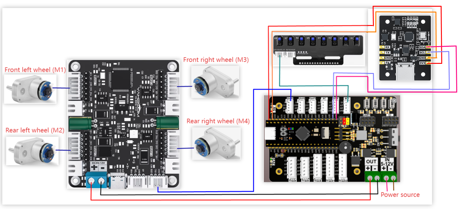
M1 -> Top left motor (left front wheel) M2 -> Bottom left motor (left rear wheel) M3 -> Top right motor (right front wheel) M4 -> Bottom right motor (right rear wheel)
Hardware Wiring:
Wiring using the MSPM0 expansion board
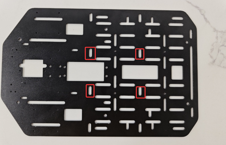
During installation and wiring, if the wire length is insufficient, the MSPM0 robot expansion board can be moved forward slightly, as shown in the diagram below.
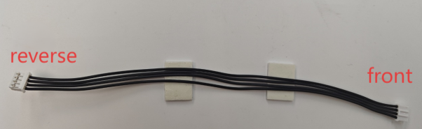
Note: The wiring used for the eight-way line-following module, and the wiring used to connect the MSPM0 robot expansion board to the four-way motor drive module, is: PH2.0-4pin ribbon cable, double-ended all-black, reverse (200mm). The direction of the reverse ribbon cable connector is shown in the following figure.
Wiring using the MSP core board
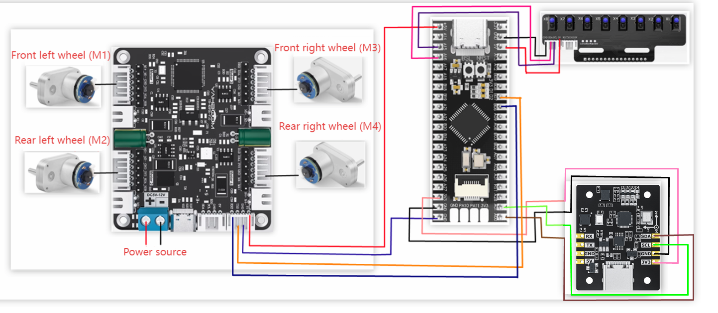
Wiring Pins:
| Four-way Motor Drive Board | MSPM0G3507/MSPM0G3519 |
|---|---|
| RX2 | PB6 |
| TX2 | PB7 |
| GND | GND |
| 5V | 5V |
| Motor | Four-way Motor Drive Board (Motor) |
|---|---|
| M2 | M- |
| V | 3V3 |
| A | H1B |
| B | H1A |
| G | GND |
| M1 | M+ |
| Eight-way Line-following Module | MSPM0G3507/MSPM0G3519 |
|---|---|
| 5V | 5V |
| SCL | PA15 |
| SDA | PA16 |
| GND | GND |
| MPU6050 | MSPM0G3507/MSPM0G3519 |
|---|---|
| VCC | 5V |
| GND | GND |
| SCL | PA1 |
| SDA | PA0 |
| SDA | PA0 |
3. Key Code Analysis
Based on the model of the motor you purchased, first modify the beginning of empty.c to your own motor model; otherwise, the car may easily go out of control during operation.
empty.c
x#define MOTOR_TYPE 5 //1:520 motor 2:310 motor 3:speed code disc TT motor 4:TT DC reduction motor 5:L type 520 motor
MOTOR_TYPE: Used to set the type of motor used. Modify the corresponding number according to the comments based on the motor you are currently using.
Because the MPU6050 is prone to angle deviation during operation, and the encoder data of different motors will be different, when running the competition questions, you need to modify the variables for judging angle and mileage in the question.c file according to your own situation. Here, using Question 3 as an example, some modifications may be needed.
question.c
xxxxxxxxxxvoid Question_Task_3(void){if(q3_first_flag == 0){// Record the angle of the first departurefirst_angle = calibratedYaw;// Start calculating mileageencoder_odometry_flag = 1;// Sound and light promptsbee_time = 300;// Start the small state machine of problem 3State_Machine.Q3_State = Q3_STATE_1;q3_first_flag = 1;}if(State_Machine.Q3_State == Q3_STATE_1){// Set the beveled target angleobject_angle = navigetion_0_360_limit(first_angle - 52);Angle_error = get_minor_arc(object_angle,calibratedYaw);PID_Value = Dir_PID(Angle_error);Motion_Car_Control(300,0,PID_Value);if(LineCheck() == BLACK && odometry_sum >= 1000){bee_time = 300;// Stop calculating mileage and clearencoder_odometry_flag = 0;odometry_sum = 0;// Enter the next state of question 3State_Machine.Q3_State = Q3_STATE_2;}}else if(State_Machine.Q3_State == Q3_STATE_2) // State 2 of question 3 (left turn grayscale tracking){LineWalking();// When the white line is detected and the angle is within the set range, it enters the next stateif((calibratedYaw < 220 && calibratedYaw > 150) && LineCheck() == WHITE){bee_time = 300;State_Machine.Q3_State = Q3_STATE_3;}}else if(State_Machine.Q3_State == Q3_STATE_3){static int Q3_state3_first_flag = 0;if(Q3_state3_first_flag == 0){// Set the beveled target angleobject_angle =navigetion_0_360_limit(first_angle - 128);Q3_state3_first_flag = 1;}// Start calculating mileageencoder_odometry_flag = 1;Angle_error = get_minor_arc(object_angle,calibratedYaw);PID_Value = Dir_PID(Angle_error);Motion_Car_Control(300,0,PID_Value);// When the black line is detected and the mileage count value is greater than or equal to 1200, enters the next stateif(odometry_sum >= 1200 && LineCheck() == BLACK){// Stop calculating mileage and clearencoder_odometry_flag = 0;odometry_sum = 0;bee_time = 300;Q3_state3_first_flag = 0;State_Machine.Q3_State = Q3_STATE_4;}}else if(State_Machine.Q3_State == Q3_STATE_4){LineWalking();// When the white line is detected and the angle is within the set range, it enters the next stateif((calibratedYaw > 340 || calibratedYaw < 20) && LineCheck() == WHITE){bee_time = 300;State_Machine.Q3_State = Q3_STATE_5;}}else{// Exit the current questionState_Machine.Q3_State = STOP_STATE;State_Machine.Main_State = STOP_STATE;// The running flag bit of question 3 is clearedq3_first_flag = 0;}}
In Q3_STATE_1: object_angle = navigetion_0_360_limit(first_angle -52);` sets the rotation angle the car needs to rotate during operation; here it's the starting angle minus 52°. If 52° isn't enough to reach the corresponding point during operation, adjust this number based on the car's deviation.
if(LineCheck() == BLACK && odometry_sum >= 1000) uses the eight-way line-following sensor to detect whether the car has reached the black line and whether the odometer count is greater than or equal to 1000. If the track conditions are poor and the eight-way line-following sensor mis-triggers, causing premature entry into the next state, increase odometry_sum.
In Q3_STATE_2: if((calibratedYaw < 220 && calibratedYaw > 150) && LineCheck() == WHITE) uses the angle from the MPU6050 to determine if the car is within the 150°-220° range and has reached the white area. However, sometimes when the car reaches this point, the angle might exceed this range, preventing it from entering the next state. In this case, you can choose to modify the angle value here; the specific amount to modify needs to be determined through actual testing.
empty.c
xxxxxxxxxx#define MOTOR_TYPE 5 //1:520 motor 2:310 motor 3:speed code disc TT motor 4:TT DC reduction motor 5:L type 520 motorint g_LinePortal_flag = 0;char buffer[80];int main(void){SYSCFG_DL_init();// SYSCFG initializationUSART_Init();// Print serial port initialization, four-channel motor communication serial port initialization// Set motor typeSet_Motor(MOTOR_TYPE);// Set motor PID parameters// Note that this PID is only adapted for Yahboom's L-type 520 motor. If it is other motors, please adjust the parameters yourselfsend_motor_PID(1.9,0.2,0.8);delay_ms(10);// Motor upload data selectionsend_upload_data(false,true,false);delay_ms(10);// Buzzer initializationPWM_Buzzer_Init();// Problem state machine initializationState_Machine_init();// Clear timer interrupt flagNVIC_ClearPendingIRQ(TIMER_0_INST_INT_IRQN);// Enable Timer InterruptNVIC_EnableIRQ(TIMER_0_INST_INT_IRQN);// Timer startDL_TimerA_startCounter(TIMER_0_INST);// After the initialization is successful, the LED light flashes twice, and the buzzer rings twiceint i = 0;for(i=0;i<4;i++){LED2_Toggle();Buzzer_Toggle();delay_ms(100);}while(1){Scheduler_Run();// Start running the task scheduler// printf("e:%d y:%d\r\n", (uint16_t)encoder_yaw, (uint16_t)yaw);// delay_ms(10);// Question selection judgmentif(g_LinePortal_flag){switch(State_Machine.Main_State){case STOP_STATE:Contrl_Pwm(0,0,0,0);break;case QUESTION_1:// Question 1Question_Task_1();break;case QUESTION_2:// Question 2Question_Task_2();break;case QUESTION_3:// Question 3Question_Task_3();break;case QUESTION_4:// Question 4Question_Task_4();break;default:break;}}}}
First, initialize all peripherals. Upon successful initialization, the LED will flash twice and the buzzer will sound twice. Then, run the task scheduler to retrieve the required data sequentially. In a while loop, continuously check if a competition topic has been selected via button presses.
MOTOR_TYPE: Change to the type of motor you are using.
app_motor.c
xxxxxxxxxxvoid Set_Motor(int MOTOR_TYPE){if(MOTOR_TYPE == 1){send_motor_type(1);// Configure motor typedelay_ms(100);send_pulse_phase(30);// Configure the reduction ratiodelay_ms(100);send_pulse_line(11);// Configure the magnetic ring wiredelay_ms(100);send_wheel_diameter(67.00);// Configure the wheel diameterdelay_ms(100);send_motor_deadzone(1900);// Configure the motor dead zonedelay_ms(100);Motor_UpdateEncoderGeometry(67.0f, 11, 30);}else if(MOTOR_TYPE == 2){send_motor_type(2);delay_ms(100);send_pulse_phase(20);delay_ms(100);send_pulse_line(13);delay_ms(100);send_wheel_diameter(48.00);delay_ms(100);send_motor_deadzone(1600);delay_ms(100);Motor_UpdateEncoderGeometry(48.0f, 13, 20);}else if(MOTOR_TYPE == 3){send_motor_type(3);delay_ms(100);send_pulse_phase(45);delay_ms(100);send_pulse_line(13);delay_ms(100);send_wheel_diameter(68.00);delay_ms(100);send_motor_deadzone(1600);delay_ms(100);Motor_UpdateEncoderGeometry(68.0f, 13, 45);}else if(MOTOR_TYPE == 4){send_motor_type(4);delay_ms(100);send_pulse_phase(48);delay_ms(100);send_motor_deadzone(1000);delay_ms(100);}else if(MOTOR_TYPE == 5){send_motor_type(1);delay_ms(100);send_pulse_phase(40);delay_ms(100);send_pulse_line(11);delay_ms(100);send_wheel_diameter(67.00);delay_ms(100);send_motor_deadzone(1900);delay_ms(100);Motor_UpdateEncoderGeometry(67.0f, 11, 40);}}
This function stores the parameters of motors sold in our store. One-click configuration can be achieved by modifying the MOTOR_TYPE parameter at the beginning of empty.c. Normally, you don't need to modify this code when using our motors. If you are using your own motor, you can choose any motor and change all the parameters to those of your own motor. If you don't understand the meaning of these parameters, you can refer to the document "4-Channel Motor Driver Board Control Instructions" to understand the specific meaning of each instruction.
4. Experimental Phenomena
After the car is powered on, the peripherals used will perform initialization operations. Please wait a moment.