yahboom
HomeLearn
Solution
Blog
Online Store
About Us
EN/中文
ROS Robot Expansion Board📖
1.Expansion board STM32 driver
  • 0. Precautions
  • 1.1 Expansion Board Introduction_V3.0
  • 1.1 Expansion Board Introduction_V1.0
  • 1.2 STM32 Development environment
  • 1.3 Button to control the buzzer to whistle
  • 1.4 FreeRTOS application
  • 1.5 Serial communication
  • 1.6 SBUS model aircraft remote control
  • 1.7 CAN bus communication
  • 1.8 RGB colorful light bar
  • 1.9 Timer interrupt to control PWM servo
  • 1.10 Control serial port servos
  • 1.11 Nine-axis attitude sensor to obtain data
  • 1.12 Control the forward and reverse rotation of the motor
  • 1.13 The timer captures the encoder data
  • 1.14.1 Robot kinematics analysis theory
  • 1.14.2 Mecanum wheel kinematics analysis
  • 1.15 PID control robot movement
  • 1.16 OLED character display
2.Python basic control
  • 2.0 Bind PCB port devices
  • 2.1 Update the firmware of the expansion board
  • 2.2 Turn off the self-starting large program at startup
  • 2.3 Install the Rosmaster driver library
  • 2.4 Buzzer whistle
  • 2.5 Control PWM servo
  • 2.6 RGB colorful light bar special effects display
  • 2.7 Control the forward and reverse rotation of the motor
  • 2.8 Control the movement of the robot
  • 2.9 Control Serial Servo
3.ROS1 Basic Course
  • 1.ROS introduction
  • 2.ROS installation
  • 3.ROS common command tools
  • 4.ROS workspace
  • 5.ROS function package
  • 6.ROS node
  • 7.ROS topic publisher
  • 8.ROS topic subscribers
  • 9.ROS service client
  • 10.ROS service server
  • 11.ROS action client
  • 12.ROS action server
  • 13.ROS custom message reception
  • 14.ROS-launch file
  • 15.ROS-TF transformation
  • 16.ROS parameter service
  • 17.ROS-rviz use
  • 18.ROS-rqt tool usage
  • 19.Topic message recording and playback
  • 20.urdf model introduction
  • 21.gazebo introduction
  • 22.ROS distributed communication
4.ROS1 robot control
  • 0. Bind PCB port devices
  • 1. Package Use the tutorial
  • 2. Package Description
  • 3. Robot keyboard control
  • 4. Robot state estimation
  • 5. Robot imu calibration
  • 6. Robot URDF Model
5.ROS2 Basic Course
  • 1.Introduction to ROS2
  • 2.ROS2 install Humble
  • 3.ROS2 development environment
  • 4.ROS2 workspace
  • 5.ROS2 function package
  • 6.ROS2 node
  • 7.ROS2 topic communication
  • 8.ROS2 service communication
  • 9.ROS2 action communication
  • 10.ROS2 custom interface message
  • 11.ROS2 parameter service case
  • 12.ROS2 meta-function package
  • 13.ROS2 distributed communication
  • 14.ROS2 DDS
  • 15.ROS2 time related API
  • 16.ROS2 common command tools
  • 17.ROS2 rviz2 use
  • 18.ROS2 rqt toolbox
  • 19.ROS2 Launch startup file configuration
  • 20.ROS2 recording and playback tool
  • 21.ROS2 URDF model
  • 22.ROS2 Gazebo simulation platform
  • 23.ROS2 TF2 coordinate transformation
6.ROS2 robot control
  • 0. Bind PCB port devices
  • 1. Package Use the tutorial
  • 2. Robot information release
  • 3. Robot keyboard control
  • 4. Robot state estimation
  • 5. Robot calibration
  • 6. URDF model
7.RDK X3 course
  • 1. Update the firmware of the expansion board
  • 2. Turn off the self-starting large program at startup
  • 3. Install the Rosmaster driver library
  • 4. Buzzer whistle
  • 5. Control PWM servo
  • 6. RGB colorful light bar special effects
  • 7. Control motor forward reverse
  • 8. Control robot movement
  • 9. Control Serial Servo
Download
  • Rules_File
  • Hardware Info
  • Code
  • 3D Model File
  • RDK Code
  • ROS2_Basic_VM
Download ZIP

Welcome to ROS Robot Expansion Board repository

1.1 Expansion Board Introduction_V1.0

1、Expansion Board Introduction

1、Expansion Board Introduction1.1、Schematic diagram of front component distribution of expansion board1.2、Schematic diagram of component distribution on the back of expansion board1.3、Analysis of common Problems on expansion modules

1.1、Schematic diagram of front component distribution of expansion board
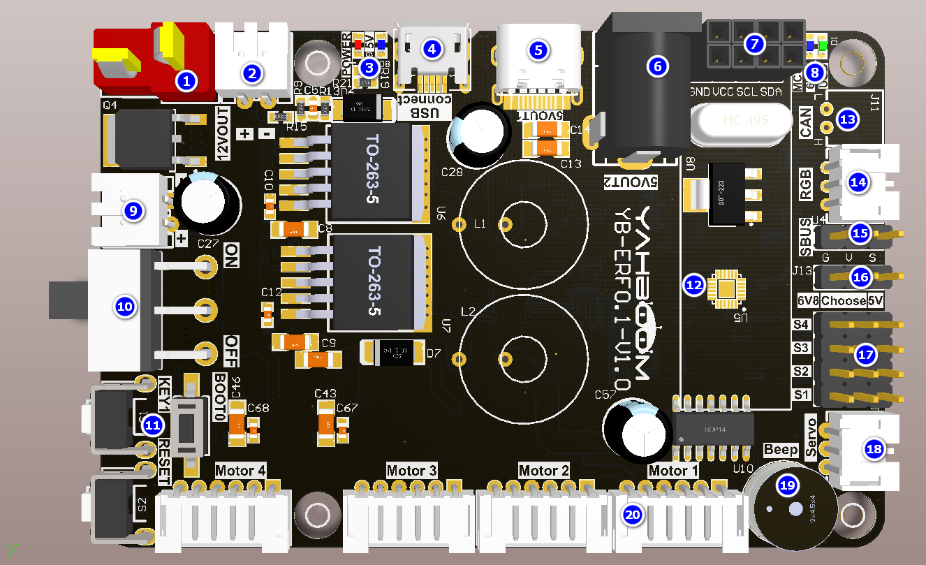
image-20220314144334865

①T DC 12V power input port: Serves as the main power input for the expansion module and connects to the DC 12V power supply or 12V battery.

②⑨DC 12V power output: provides 12V DC power.

③Power indicator: indicates whether the power supply is normal.

④Micro USB data interface: connect the host communication and burning program.

⑤Type-c interface: provides DC 5V and cannot communicate only with power supply.

⑥DC 5V output interface: power Jetson Nano.

⑦I2C interface: Connects to external I2C devices, such as OLED screens.

⑧Indicators: data indicator and 6.8V voltage indicator.

⑩DC 12V power switch: main power switch.

⑪Key: KEY1: user function key, which can be customized by programming. RESET: RESET button for the onboard microcontroller. Button BOOT0: BOOT0 button for the onboard microcontroller to enter the burning mode.

⑫Nine-axis attitude sensor: Provides the current attitude of the expansion board.

⑬CAN interface: Connects to a CAN device.

⑭RGB bright light bar interface: connect RGB bright light bar.

⑮SBUS interface: connect the receiver of remote control of model airplane.

⑯PWM steering gear voltage switching: change the position of jumper cap can choose 6.8V or 5V voltage for PWM steering gear power supply.

⑰PWM steering gear interface: can connect to 6.8V or 5V voltage PWM steering gear, select the corresponding voltage on ⑯ persons according to the steering gear voltage.

⑱Serial actuator interface: connects to the serial actuator arm.

⑲Buzzer: Used for whistling alarm.

⑳Four-way motor connection port: connect four motors. Please refer to the corresponding course documents according to the connection mode of different models.


1.2、Schematic diagram of component distribution on the back of expansion board
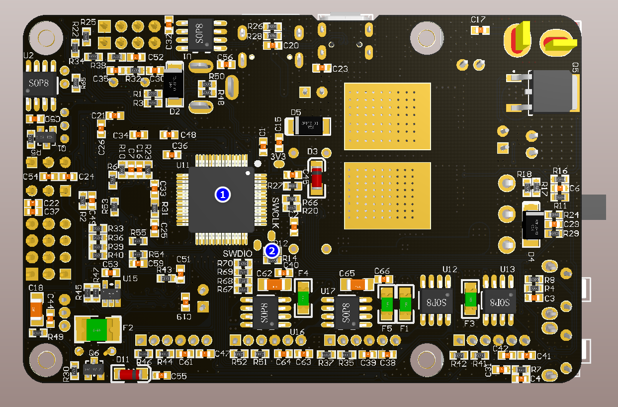
image-20220314144537523

①Onboard microcontroller: mainly responsible for the control of peripherals on the expansion board, such as buzzer, motor drive, etc.

②Debugging interface: connects to the SW interface on the ST-link or J-link for debugging single-chip microcomputer or downloading single-chip firmware. Note: There is no warranty after welding.


1.3、Analysis of common Problems on expansion modules

Q : How does the Jetson Nano control the expansion pad? How do I communicate with the expansion board?

A:The Jetson Nano sends serial port data to the expansion board via the USB port. The expansion board integrates a single chip microcomputer to receive and parse the serial port data, and then processes the specific commands to be executed.

Q : How does the robot power? Will the Jetson Nano need additional power?

A:The car is equipped with a battery pack before delivery. Plug the battery pack into the T-type interface of DC 12V power supply on the expansion board and turn on the main power switch. The expansion board integrates a voltage conversion chip to provide DC 5V power supply and transmits power to Jetson Nano through the DC 5V power cord.

Q : Which functions on the expansion board are managed by the microcontroller?

A:The SCM management on the expansion board includes: mechanical arm, active buzzer, attitude sensor, PWM steering gear head, motor, RGB bright lights, KEY1, RESET, SBUS interface, CAN interface, etc.

Q : How to update SCM firmware on expansion module? Why to update the MCU firmware?

A:The microcontroller integrated with the expansion module has burned its firmware before delivery. Do not update the firmware if it is not necessary. If you need to update the firmware, please refer to the firmware update tutorial to update the MCU firmware.


Expansion Board Introduction_V3.0
STM32 Development environment

COMPANY

  • About us
  • Team Style
  • Blog

LEARNING & EXPLORATION

  • Tutorials
  • Edge AI hardware
  • Educational robots
  • Embedded intelligent hardware

WHERE TO BUY

  • Yahboom Online Store
  • Amazon
  • Alibaba
  • AliExpress
  • Mercado

TECHNOLOGY SUPPORT

  • Email: support@yahboom.com

BE A DISTRIBUTOR

  • Email: sales@yahboom.com
QR Code

Copyright © 2017-2026 Yahboom. All Rights Reserved.

EN/中文