Welcome to L-Type Motor repository
3. Development board pin assignment
Development board pin assignment
Development board pin assignment1. Interface introduction:2. Physical picture3. Schematic diagram4. Pin index1. RGB light2. Buzzer3. Button4. CCD camera5. Motor6. Serial port7. Ultrasonic module8. Electromagnetic tracking module9. Four-way tracking module10. PS2 controller11. OLED module12. PWM steering gear13. Gyroscope14. Infrared remote control
1. Interface introduction:
The following is the interface diagram of the STM32 expansion board
The external interfaces on the expansion board are:
Power input interface, SWD interface, serial port interface, OLED, type-C communication interface, PWM servo interface, function buttons, electromagnetic tracking interface, four-way line patrol interface, CCD camera interface, PS2 handle interface, pin header interface, ultrasonic module
2. Physical picture
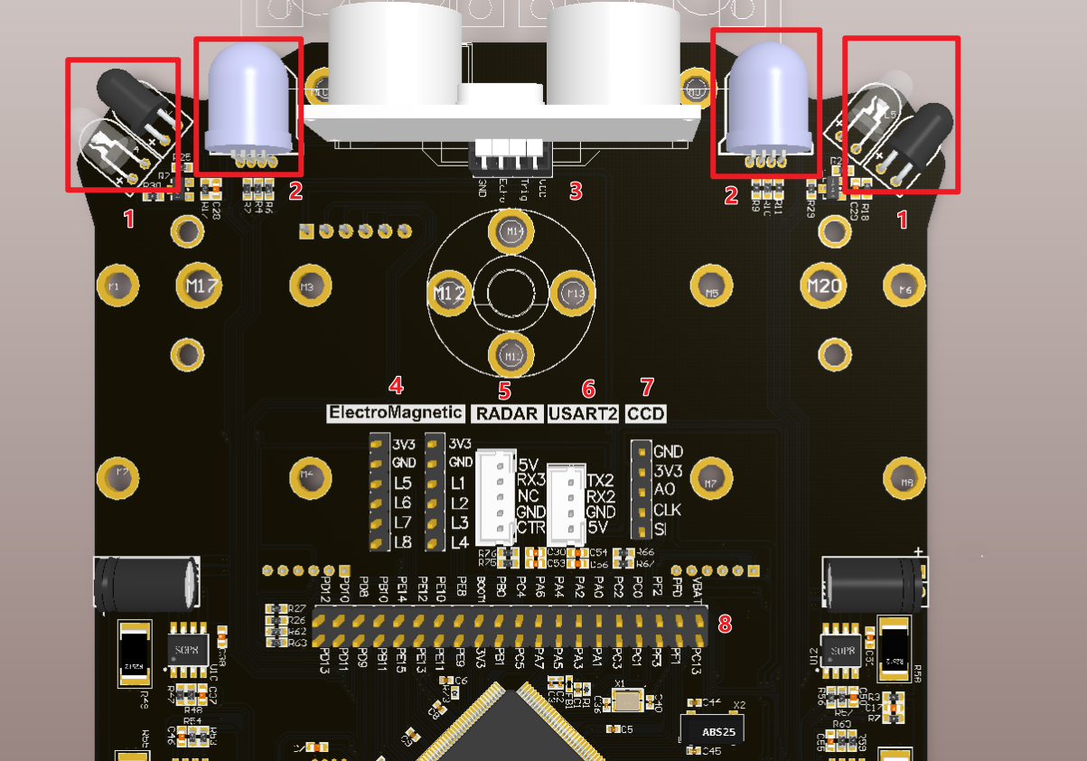
- Infrared obstacle avoidance module
- RGB searchlight
- Ultrasonic module interface: used to connect external ultrasonic module
- Electromagnetic tracking interface: used to connect external electromagnetic line tracking sensors
- X3 radar interface: used to connect external YDLIDAR X3 radar
- Serial port 2 interface: can be used to connect external k210 vision module
- Linear CCD camera interface: used for external linear CCD camera
- Pins derived from STM32f103ZET6.
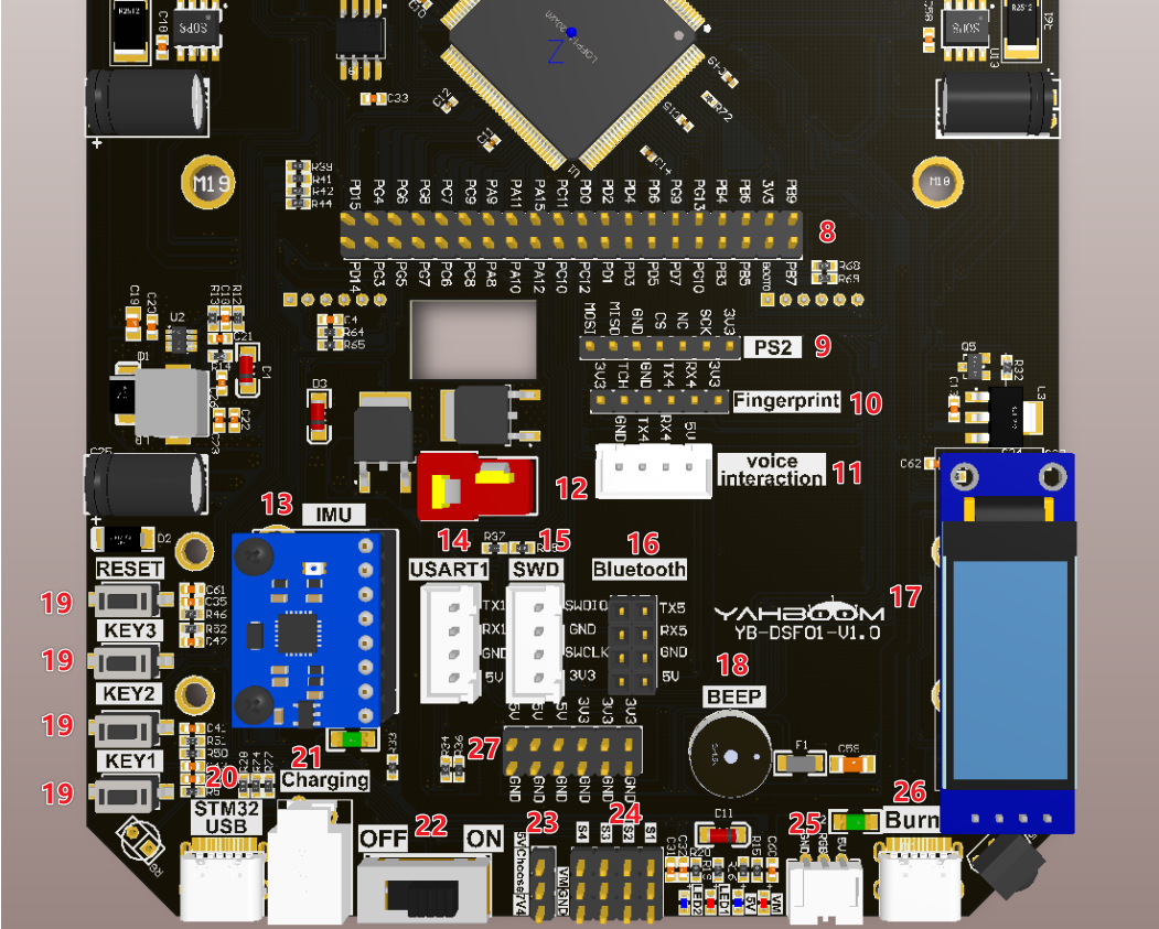
PS2 controller receiver interface: used to connect external PS2 controller receiver
Fingerprint module interface: used for external fingerprint module
Voice interaction module interface: used to connect external voice interaction module
T-shaped DC 7.4V power input interface: used as the main power input of the expansion board, connected to the DC 7.4V power supply or 7.4V battery.
MPU6050 interface: used to connect external MPU6050 module
Serial port 1 interface: used to debug the serial port
SWD interface: used for microcontroller debugging
Bluetooth module interface: used for external Bluetooth module
OLED screen interface: external 0.91-inch OLED LCD screen
Buzzer: Onboard active buzzer.
Buttons KEY1, KEY2, KEY3: user function buttons, which can be programmed to achieve customized functions. Button RESET: Onboard microcontroller reset button.
STM32-USB device interface: can realize STM32 USB function
Charging interface: can charge external batteries
On/off button: The main on/off button of the expansion board
PWM servo voltage switching: Change the position of the jumper cap to select 7.4V or 5V voltage to power the PWM servo.
PWM servo interface: It can connect to 7.4V or 5V voltage PWM servo. You need to select the corresponding voltage in 23 according to the servo voltage.
RGB light strip interface: connect RGB light strip
Type-C data interface: Programming for microcontroller
(3.3/5V) output interface: output 3.3V/5V voltage to the outside
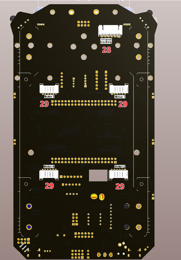
- Four-way tracking module interface: used for external four-way tracking module
- Motor interface: for external 310 motor
3. Schematic diagram
There are corresponding pin silkscreens on the expansion board, and you can directly connect them according to the silkscreens.


4. Pin index
1. RGB light
| Schematic identifier | Control pin | Specific meaning |
|---|---|---|
| RRGB-R | PE2 | Right RGB light, control red |
| RRGB-G | PE3 | Right RGB light, control green |
| RRGB-B | PE4 | Right RGB light, control blue |
| LRGB-R | PG1 | Left RGB light, control red |
| LRGB-G | PE7 | Left RGB light, control green |
| LRGB-B | PG2 | Left RGB light, control blue |
2. Buzzer
Control principle
High and low level control active buzzer sound
| Schematic identifier | Control pin | Specific meaning |
|---|---|---|
| Buzzer | PG12 | Control active buzzer sound |
3. Button
| Schematic identifier | Control pin | Specific meaning |
|---|---|---|
| KEY1 | PG3 | Key 1 |
| KEY2 | PG4 | Key 2 |
| KEY3 | PG5 | Button 3 |
4. CCD camera
| Schematic identifier | Control pin | Specific meaning |
|---|---|---|
| CCD-SI | PF4 | CCD camera signal acquisition terminal |
| CCD-CLK | PF5 | CCD camera control clock terminal |
| CCD-AO | PF6 | CCD gray value output terminal |
5. Motor
| Schematic identifier | Control pin | Specific meaning |
|---|---|---|
| M1A | PC6 | M1 motor phase A |
| M1B | PC7 | M1 motor B phase |
| M2A | PC8 | M2 motor phase A |
| M2B | PC9 | M2 motor B phase |
| M3A | PE9 | M3 motor phase A |
| M3B | PE11 | M3 motor phase B |
| M4A | PE13 | M4 motor phase A |
| M4B | PE14 | M4 motor phase B |
6. Serial port
| Schematic identifier | Control pin | Specific meaning |
|---|---|---|
| USART1_TX | PA9 | Serial port 1 output |
| USART1_RX | PA10 | Serial port 1 receiving end |
| USART2_TX | PD5 | Serial port 2 output |
| USART2_RX | PD6 | Serial port 2 receiving end |
| USART3_TX | PD8 | Serial port 3 output |
| USART3_RX | PD9 | Serial port 3 receiving end |
| USART4_TX | PC10 | Serial port 4 receiving end |
| USART1_RX | PC11 | Serial port 4 output |
| USART5_TX | PC12 | Serial port 5 receiving end |
| USART1_RX | PD2 | Serial port 5 output |
7. Ultrasonic module
| Schematic identifier | Control pin | Specific meaning |
|---|---|---|
| TRIG | PF11 | Ultrasonic module control terminal |
| ECHO | PF12 | Ultrasonic module receiving end |
8. Electromagnetic tracking module
| Schematic identifier | Control pin | Specific meaning |
|---|---|---|
| ADC-L1 | PC0 | Electromagnetic tracking module output |
| ADC-L2 | PC1 | Electromagnetic tracking module output |
| ADC-L3 | PC2 | Electromagnetic tracking module output |
| ADC-L4 | PC3 | Electromagnetic tracking module output |
9. Four-way tracking module
| Schematic identifier | Control pin | Specific meaning |
|---|---|---|
| X1 | PF13 | Four-channel tracking signal output terminal |
| X2 | PF14 | Four tracking 21 signal output terminals |
| X3 | PF15 | Four-channel tracking 3-channel signal output terminal |
| X4 | PG0 | Four-channel tracking 4-channel signal output terminal |
10. PS2 controller
| Schematic identifier | Control pin | Specific meaning |
|---|---|---|
| PS2-CS | PA4 | PS controller receiver |
| PS2-SCK | PA5 | PS controller receiver |
| PS2-MISO | PA6 | PS controller receiver |
| PS2-MOSI | PA7 | PS controller receiver |
11. OLED module
| Schematic identifier | Control pin | Specific meaning |
|---|---|---|
| I2C1_SCL | PB6 | Clock line |
| I2C1_SDA | PB7 | Data line |
12. PWM steering gear
| Schematic identifier | Control pin | Specific meaning |
|---|---|---|
| S1 | PB0 | PWM servo interface |
| S2 | PB1 | PWM servo interface |
| S3 | PD14 | PWM servo interface |
| S4 | PD15 | PWM servo interface |
13. Gyroscope
| Schematic identifier | Control pin | Specific meaning |
|---|---|---|
| ADO | PE1 | Empty pin |
| INT | PE0 | Empty pin |
| I2C1_SCL | PB6 | Clock line |
| I2C1_SDA | PB7 | Data line |
14. Infrared remote control
| Schematic identifier | Control pin | Specific meaning |
|---|---|---|
| HS0038B | PG11 | Signal output |