Welcome to L-Type Motor repository
10. Car line patrol
Car line patrol
Car line patrol1. Software-Hardware2. Brief principle1. Hardware schematic diagram2. Physical connection diagram3. Control principle3. Main functions4. Experimental Phenomenon
This tutorial is a comprehensive experiment combining multiple peripherals. You can first understand a single peripheral before performing this experiment.
1. Software-Hardware
STM32F103CubeIDE
STM32 Robot Development Board
Four-way tracking module, 310 motor*4: external
Type-C data cable or ST-Link
Download programs or simulate the development board
2. Brief principle
1. Hardware schematic diagram
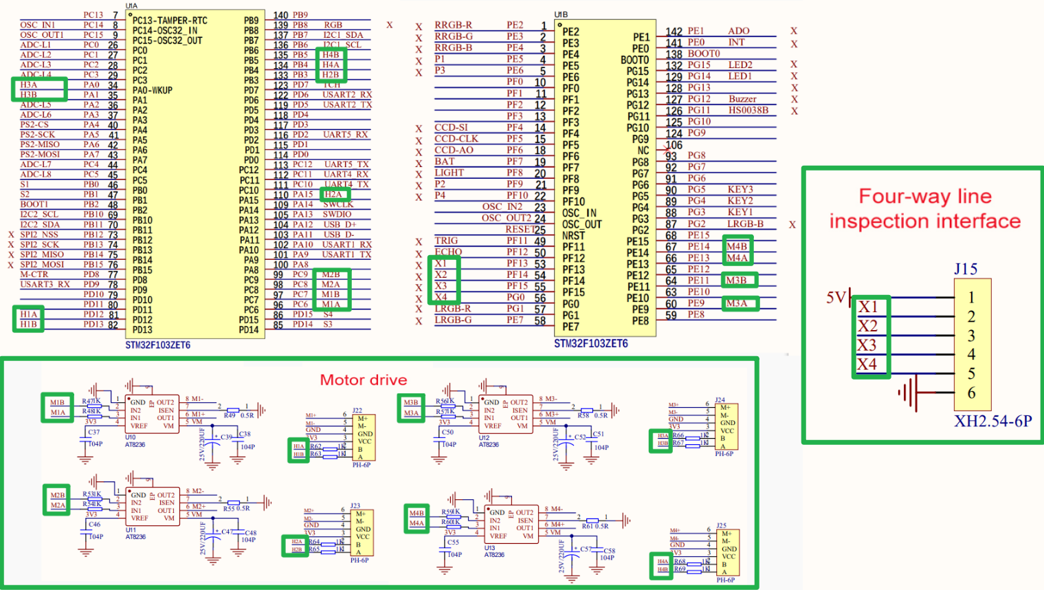
2. Physical connection diagram
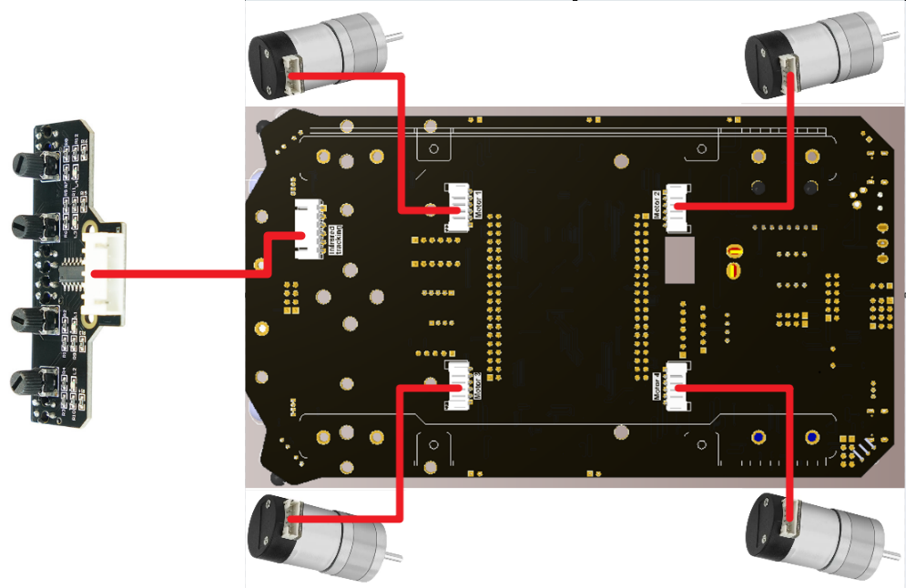
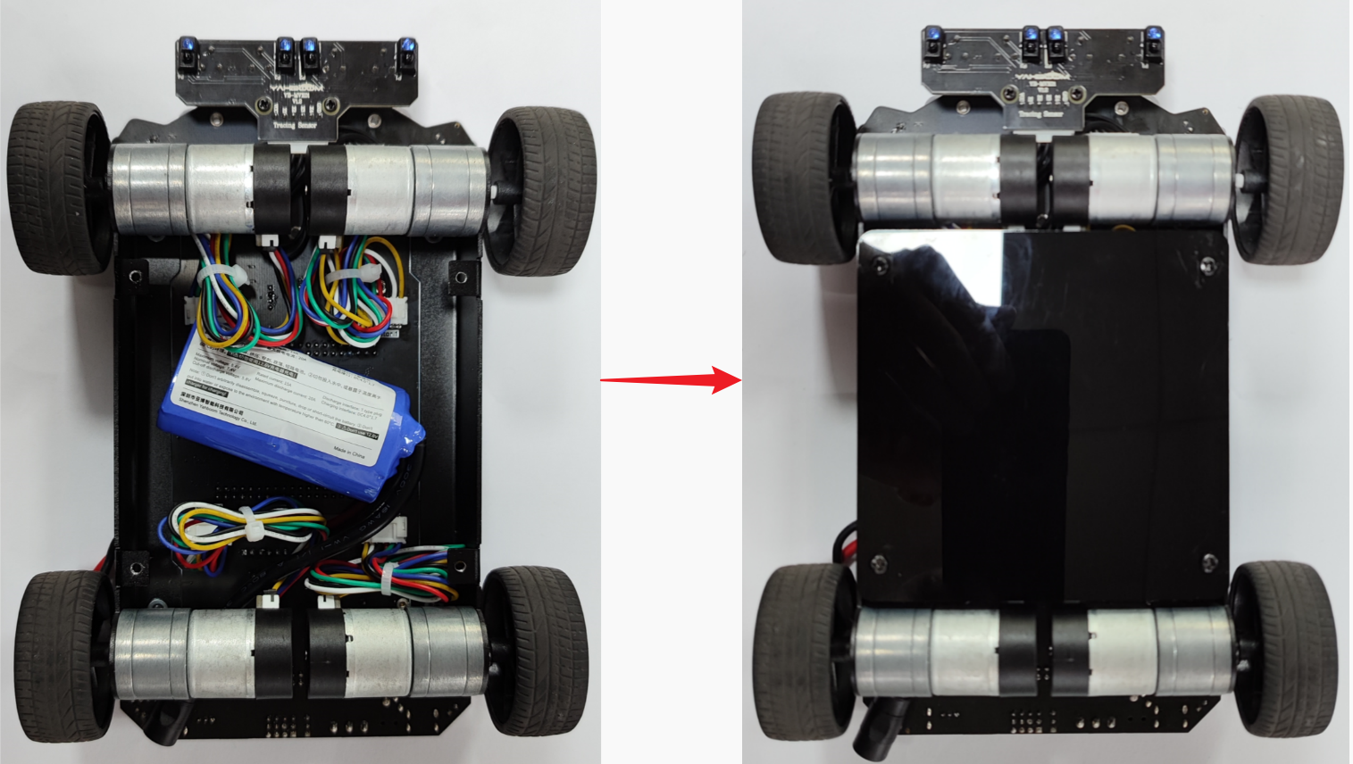
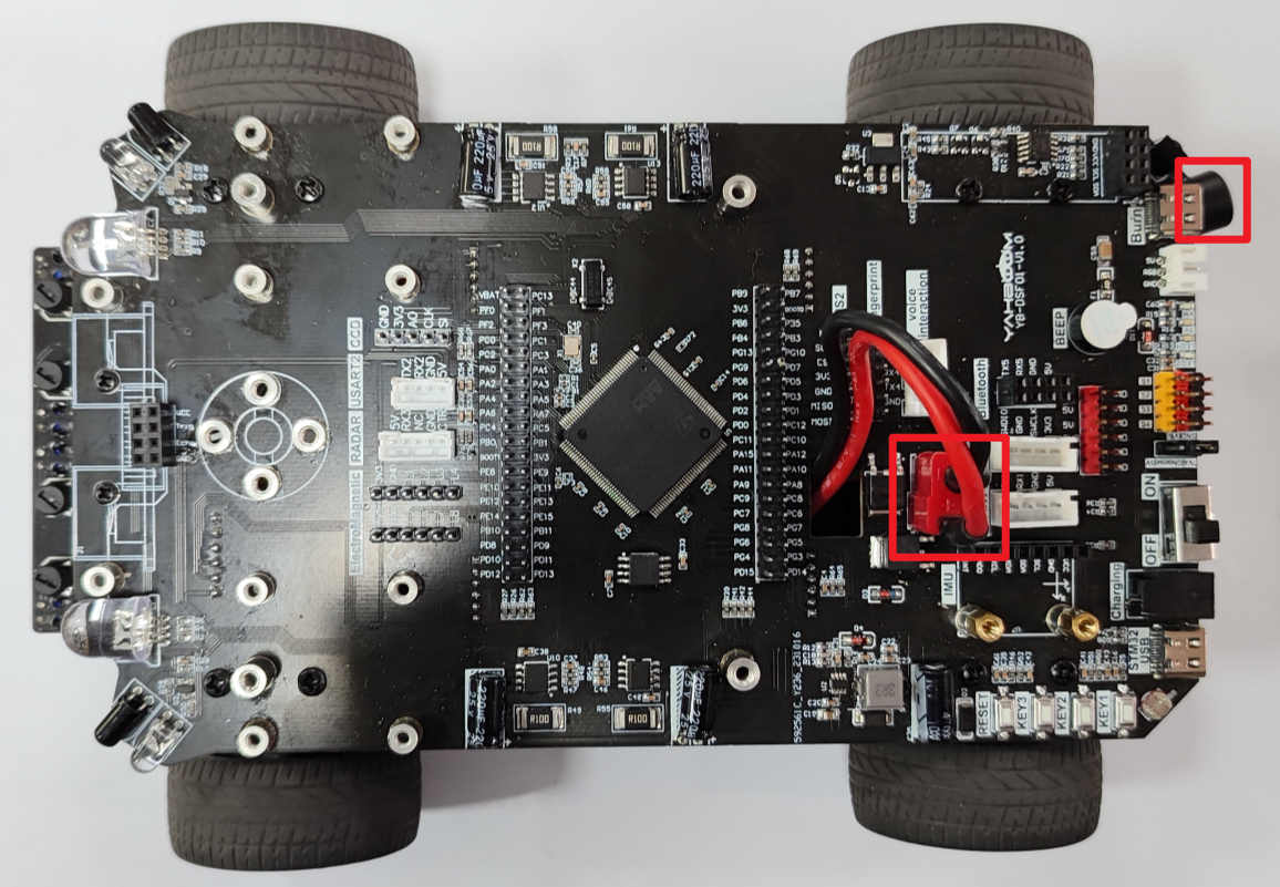
- Battery Pack Installation
3. Control principle
The real-time position of the car is obtained through the four-way line patrol module, and the motion status of the car is adjusted according to the position.
xxxxxxxxxxThe four-way line patrol module can obtain the position of the car's front on the route. We can read the levels of the four interfaces to determine the position of the car:If the car deviates to the left relative to the route, we call the function that controls the car to turn right (right rotation) in the function;If the car veers to the right relative to the route, we call the function that controls the car to turn left (left-hand rotation) in the function;If the car is in the middle of the line following module, we control the car to move forward.
The following figure shows the common detection situation of the four-channel tracking module:
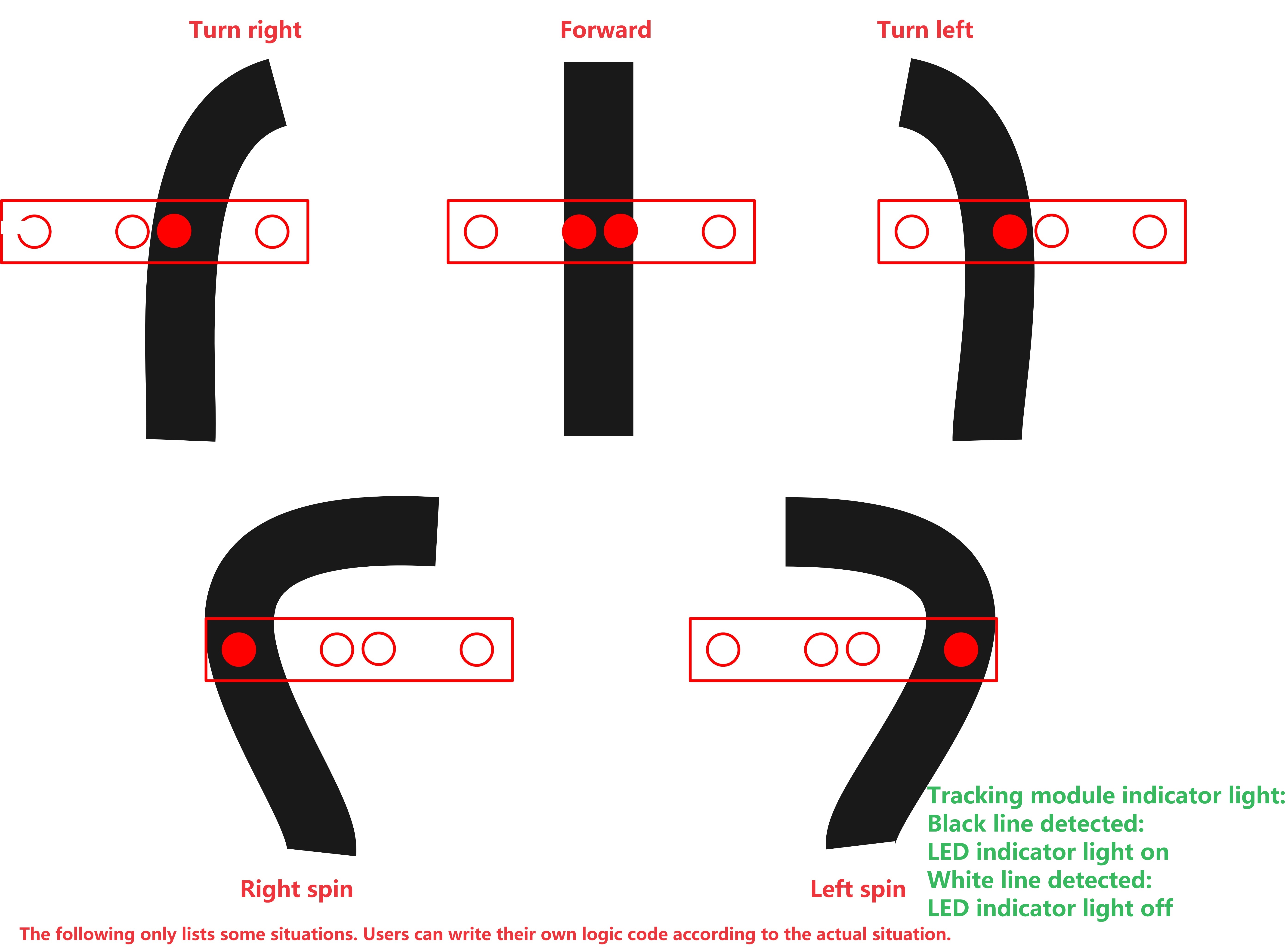
- Program flow chart

According to the information fed back by the four-way tracking module, we can combine four motors to realize the line-following car:
| External modules | Functions |
|---|---|
| Four-way line patrol module | External information collection: detect the position of the line patrol module on the route |
| Motor | Motion Control |
- Four-channel line patrol module detects black and white lines and feeds back information
| Four-way line patrol module | Indicator light | Output level |
|---|---|---|
| Black line detected | Light on | Low level |
| White line detected | Light off | High level |
3. Main functions
This tutorial does not use PID to control the movement of the car
Function: car_irtrack
| Function prototype | void car_irtrack(void) |
|---|---|
| Function description | Control the steering of the car based on the line patrol module information |
| Input parameters | None |
| Return value | None |
Function: Motion_Set_Speed
| Function prototype | void Motion_Set_Speed (int16_t speed_m1, int16_t speed_m2, int16_t speed_m3, int16_t speed_m4) |
|---|---|
| Function description | Control the steering and speed of the four motors of the car |
| Input parameter 1 | speed_m1: Motor1 steering and speed |
| Input parameter 2 | speed_m2: Motor2 steering and speed |
| Input parameter 3 | speed_m3: Motor3 steering and speed |
| Input parameter 4 | speed_m4: Motor4 steering and speed |
| Return value | None |
Function: PID_Set_Motor_Target
| Function prototype | void PID_Set_Motor_Target(uint8_t motor_id, float target) |
|---|---|
| Function description | Use PID to control the car speed |
| Input parameter 1 | motor_id: motor number |
| Input parameter 2 | target: target speed |
| Return value | None |
xxxxxxxxxxFor the underlying driver, you can refer to the tutorials in Chapter 3 and Chapter 4.For the application layer, you can read the source code in the project file yourself
4. Experimental Phenomenon
After successfully downloading the program, press the RESET button on the development board to observe the effect of the car!
xxxxxxxxxxFor program download, please refer to [2. Development environment construction and use: program download and simulation]
Phenomenon:
The car follows the route on the map (the code we provide can only follow simple routes).
Because the code only analyzes common line following situations, the demonstration is straight line and turning situations;Users can add line patrol judgment situations by themselves to make line patrol more accurate!