Welcome to L-Type Motor repository
1.AT8236 drive tutorials
AT8236 drive tutorials
I. Learning Objectives
Read the motor encoder data.
II. Hardware Connection
MSPM0G3519 and AT8236 pin connection
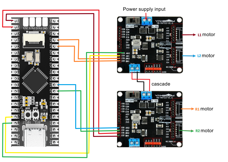
L1 motor:
| MSPM0G3519 | AT8236 |
|---|---|
| PA12 | AIN1 |
| PA13 | AIN2 |
| PA14 | E1A |
| PA15 | E1B |
L2 motor:
| MSPM0G3519 | AT8236 |
|---|---|
| PA26 | BIN1 |
| PA27 | BIN2 |
| PA24 | E2A |
| PA25 | E2B |
Note: You can use the ttl module, or just use the Type-C port of the MSPM0G3519 to connect to the computer.
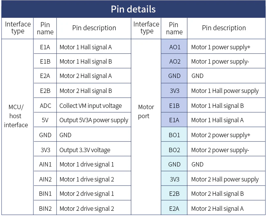
AT8236 motor driver module pin description:
III. Program Description
This example sets the baud rate of the serial port printing to 115200 bps.
bsp_at8236.h
x#ifndef __BSP_TB6612_H_#define __BSP_TB6612_H_#include "ti_msp_dl_config.h"void init_motor(void);void L1_control(uint16_t motor_speed,uint8_t dir);void L2_control(uint16_t motor_speed,uint8_t dir);void R1_control(uint16_t motor_speed,uint8_t dir);void R2_control(uint16_t motor_speed,uint8_t dir);#endif
Define four motor control functions.
bsp_at8236.c
xxxxxxxxxxvoid L1_control(uint16_t motor_speed,uint8_t dir){if(dir){DL_TimerA_setCaptureCompareValue(PWM_L1_INST, motor_speed, DL_TIMER_CC_0_INDEX);DL_TimerA_setCaptureCompareValue(PWM_L1_INST, 0, DL_TIMER_CC_1_INDEX);}else{DL_TimerA_setCaptureCompareValue(PWM_L1_INST, 0, DL_TIMER_CC_0_INDEX);DL_TimerA_setCaptureCompareValue(PWM_L1_INST, motor_speed, DL_TIMER_CC_1_INDEX);}}
The L1_control function is used to control the speed and direction of the L1 motor by adjusting the duty cycle of the PWM signal.
motor_speed and dir represent the motor speed and motor direction of the motor respectively.
bsp_delay.h
xxxxxxxxxx#ifndef __BSP_DELAY_H_#define __BSP_DELAY_H_#include "ti_msp_dl_config.h"void delay_ms(unsigned int ms);#endif
Define a delay function delay_ms
bsp_delay.c
xxxxxxxxxx#include "bsp_delay.h"#include "ti_msp_dl_config.h"volatile unsigned int delay_times = 0;volatile unsigned int getspeed = 10;//Get speed flag, read once every 10msextern volatile int32_t gEncoderCount_L1,gEncoderCount_L2;extern int speed,speed2;//Accurate ms delay implemented with the SysTick timervoid delay_ms(unsigned int ms)//1ms timing{delay_times = ms;while( delay_times != 0 );}//SysTick timer interrupt service functionvoid SysTick_Handler(void){if( delay_times != 0 ){delay_times--;}if( getspeed != 0 ){getspeed--;}else{getspeed = 10;speed = gEncoderCount_L1;speed2 = gEncoderCount_L2;gEncoderCount_L1 = 0;//clear to 0gEncoderCount_L2 = 0;//clear to 0}}
It processes the counts of two encoders (L1 and L2) and updates their speed measurements every 10 milliseconds.
bsp_enconder.c
xxxxxxxxxxvoid GROUP1_IRQHandler(void){//Get interrupt signalgpioA = DL_GPIO_getEnabledInterruptStatus(GPIOA,L1_Enconder_A_pin_14_PIN | L1_Enconder_B_pin_15_PIN|L2_Enconder_A_pin_24_PIN|L2_Enconder_B_pin_25_PIN);//If the interrupt is generated by GPIO_EncoderA_PIN_0_PINif((gpioA & L1_Enconder_A_pin_14_PIN) == L1_Enconder_A_pin_14_PIN){//Pin14 rising edge, check Pin15 level: low means reverse rotation, high means forward rotationif(!DL_GPIO_readPins(GPIOA,L1_Enconder_B_pin_15_PIN))//P15 is low{gEncoderCount_L1--;}else//P15 is high{gEncoderCount_L1++;}}else if((gpioA & L1_Enconder_B_pin_15_PIN) == L1_Enconder_B_pin_15_PIN){//Pin15 rising edgeif(!DL_GPIO_readPins(GPIOA,L1_Enconder_A_pin_14_PIN))//P14 is low{gEncoderCount_L1++;}else//P14 is high{gEncoderCount_L1--;}}
Used to handle encoder interrupts, read and update encoder data.
bsp_usart.h
xxxxxxxxxx#ifndef __BSP_USART_H_#define __BSP_USART_H_#include "ti_msp_dl_config.h"#include "bsp_delay.h"void uart0_send_char(char ch);void uart0_send_string(char* str);#endif
A header file for serial communication is defined, which is mainly used to implement simple character and string sending functions.
bsp_usart.c
xxxxxxxxxx//Send a single character via serial portvoid uart0_send_char(char ch){//Wait while serial port 0 is busy; send the character when it is freewhile( DL_UART_isBusy(MYUART_INST) == true );//Send a single characterDL_UART_Main_transmitData(MYUART_INST, ch);}//Send a string via serial portvoid uart0_send_string(char* str){//Current string address is not at the end and the string start address is not nullwhile(*str!=0&&str!=0){//Send the character at the string start address, and increment the start address after sendinguart0_send_char(*str++);}}//Serial port interrupt service functionvoid MYUART_INST_IRQHandler(void){//If a serial port interrupt occursswitch( DL_UART_getPendingInterrupt(MYUART_INST) ){case DL_UART_IIDX_RX://If it is a receive interrupt//Save the received data into a variableuart_data = DL_UART_Main_receiveData(MYUART_INST);//Send the saved data back outuart0_send_char(uart_data);break;default://Other serial port interruptsbreak;}}
Use USART for serial communication. Includes the functions of sending single characters, sending strings, and a USART interrupt service routine.
main.c
xxxxxxxxxxint main(void){SYSCFG_DL_init();//Clear the serial port interrupt flagNVIC_ClearPendingIRQ(MYUART_INST_INT_IRQN);//Enable the serial port interruptNVIC_EnableIRQ(MYUART_INST_INT_IRQN);//NVIC_EnableIRQ(GPIO_MULTIPLE_GPIOA_INT_IRQN);//Enable external interruptinit_motor();//Start the motor timerwhile (1){sprintf(buf,"speed1(10ms):%d\t speed2(10ms):%d\r\n",speed,speed2);uart0_send_string(buf);L1_control(600,0);//0-1000L2_control(400,1);//0-1000delay_ms(300);}}
Continuously update the speed of the two motors, and set the speed and direction of motors L1 and L2 respectively through the L1_control and L2_control functions. Use the sprintf function to format a message that contains the current speed information of the two motors, and send this message through the uart0_send_string function to monitor or record the status of the motors.
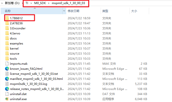
Note: The project source code must be placed in the SDK path for compilation,
For example, path: D:\TI\M0_SDK\mspm0_sdk_1_30_00_03\1.TB6612