Welcome to L-Type Motor repository
9. PS2 controller test
PS2 controller test
PS2 controller test1. Software-Hardware2. Brief principle1. Hardware schematic diagram2. Physical connection diagram3. Control principle3. Project configuration1. Description2. Pin configuration4. Main functions1. User function5. Experimental phenomena
This tutorial demonstrates: How to connect an external PS2 controller receiver to the expansion board and print the key values of the controller through the serial port.
1. Software-Hardware
STM32F103CubeIDE
STM32 Robot Development Board
PS2 controller and receiver
Type-C data cable or ST-Link
Download programs or simulate the development board
Serial Assistant
Receive serial port data and print
2. Brief principle
1. Hardware schematic diagram
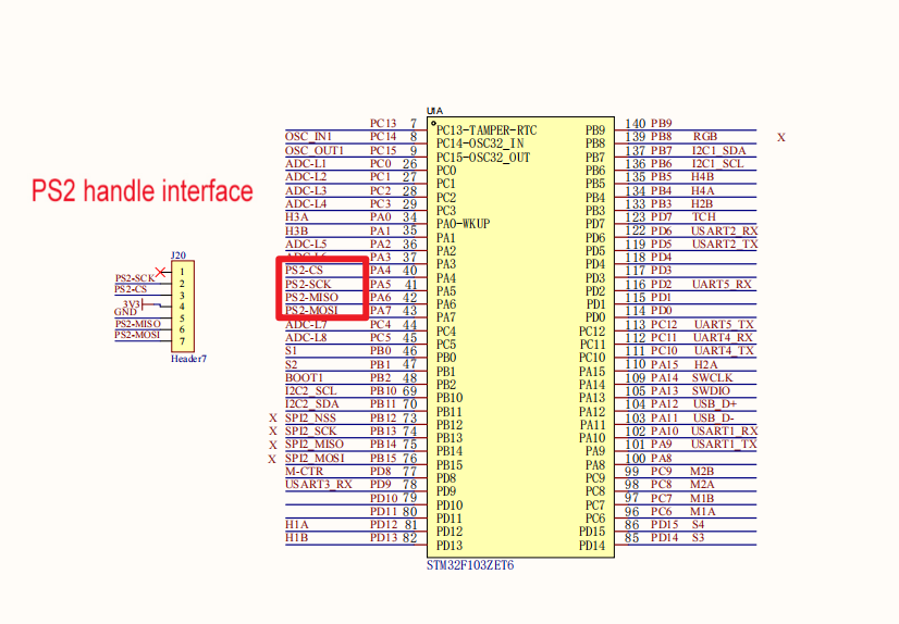
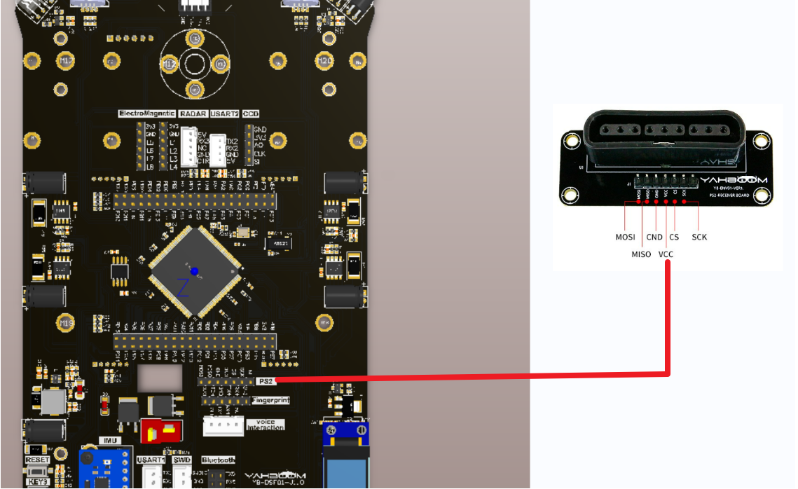
2. Physical connection diagram
3. Control principle
| (Schematic name) | Control pin | Specific meaning |
|---|---|---|
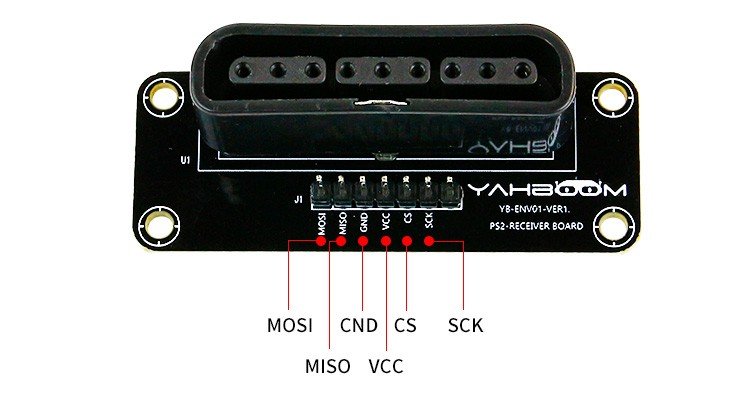
| PS2-CS | PA4 | Chip select signal |
| PS2-SCK | PA5 | Serial clock signal |
| PS2-MISO | PA6 | Host input and slave output signal terminal |
| PS2-MOSI | PA7 | Host output slave input signal terminal |
SPI communication protocol:
The full English name of SPI is Serial Peripheral Interface, which as the name suggests is a serial peripheral interface. SPI is a synchronous serial communication interface specification mainly used for short-distance communication in embedded systems. The interface was developed by Motorola in the mid-1980s and later became an industry standard.
SPI devices communicate in full-duplex mode, which is a master-slave mode between a host and one or more slaves. The host is responsible for the initialization frame. This data transmission frame can be used for both read and write operations. The chip select line can select one from multiple slaves to respond to the host's request.

data transmission:
In SPI communication, the SPI master device transmits data to the SPI slave device through the SCLK line at the frequency supported by the slave device. This also means that the slave device cannot actively send data to the host device, and can only send data to the slave device in polling mode. Or the slave device actively notifies the host of data arrival through an IO port.
In each clock cycle of SPI, a full-duplex data transmission is performed. When the host sends 1 bit through the MOSI line, the slave will also send 1 bit data out through the MISO line after reading it. This means that this communication sequence is maintained even if only simplex communication is performed.
The timing diagram is as follows:
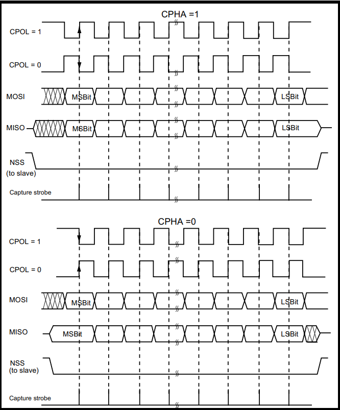
SPI communication process:
- The SPI master first pulls the SS or CS line low to inform the SPI slave to start communication.
- The host notifies the slave of the upcoming read and write operations by sending the SCLK clock signal. The SCLK clock signal here is determined by the SPI mode whether it is high level or low level, which will be introduced later.
- The host (Master) writes the data to be sent to the sending data buffer area (Memory). The buffer area passes through the shift register (0~7). The serial shift register shifts the bytes one by one through the MOSI signal line. Out and transmitted to the slave, at the same time, the data received by the MISO interface is moved to the receiving buffer area bit by bit through the shift register.
- The slave (Slave) also returns the contents of its own serial shift register (0~7) to the host through the MISO signal line. At the same time, the data sent by the host is received through the MOSI signal line, so that the contents of the two shift registers are exchanged.
PS2 Controller: The PS2 controller consists of two parts: controller and receiver. The controller is mainly responsible for sending button information; the receiver is connected to the microcontroller (also called the host) and is used to receive information from the controller and pass it to The microcontroller can also send commands to the handle through the receiver and configure the sending mode of the handle.
Mode switching: Press the "MODE" button and the handle can be configured to "Red light mode" or "Green light mode".
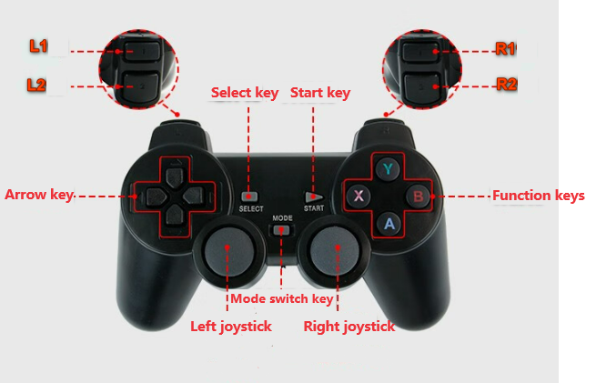
Introduction to handle buttons:
| Function keys | Corresponding key values |
|---|---|
| L1 | 11 |
| L2 | 9 |
| R1 | 12 |
| R2 | 10 |
| Direction keys (up, down, left, right) | 5/7/8/6 |
| Function keys (X/A/Y/B) | 16/15/13/14 |
| Select key | 1 |
| Start key | 4 |
| Pin | Function |
|---|---|
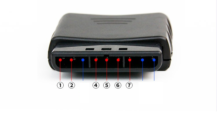
| DI/DAT | Signal flow direction, from controller to host |
| DO/CMD | Signal flow direction, from host to handle |
| GND | Power ground |
| VDD | Receiver working power supply: 3-5V |
| CS/SEL | Controller trigger signal |
| CLK | Clock signal |
3. Project configuration
1. Description
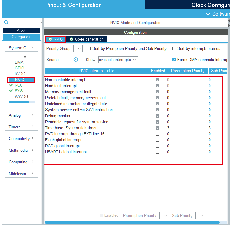
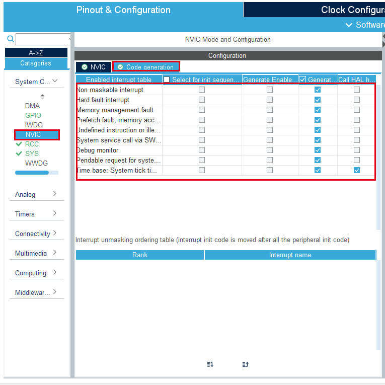
Omitted project configuration part: New project, chip selection, project configuration, SYS of pin configuration, RCC configuration, clock configuration and project configuration content
Please refer to [2. Development environment construction and use: STM32CubeIDE installation and use] to understand how to configure the omitted parts of the project.
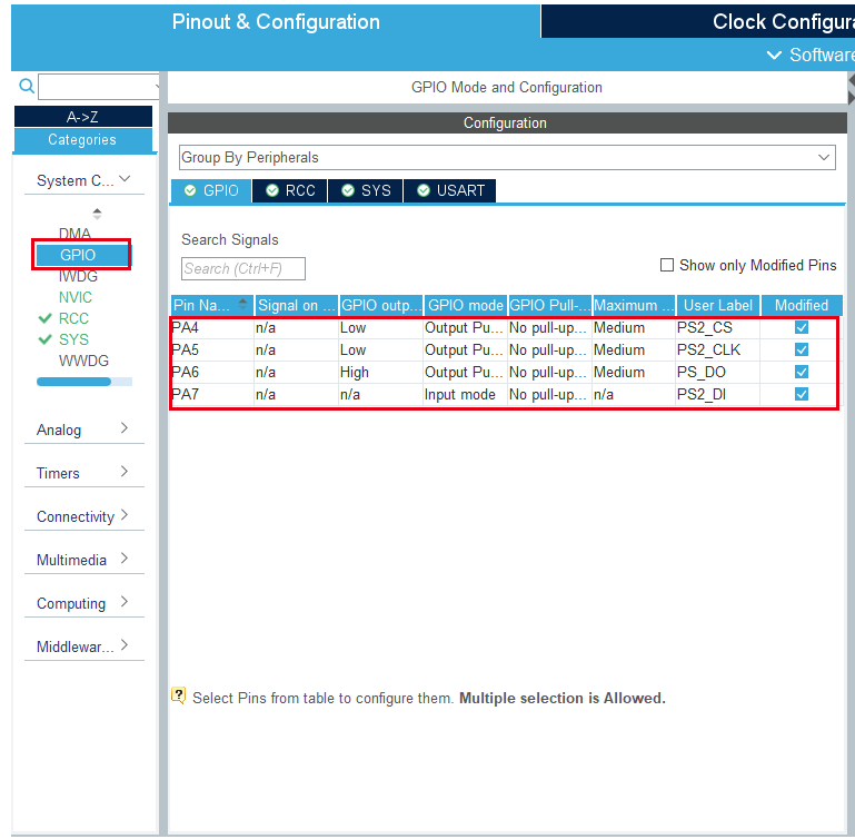
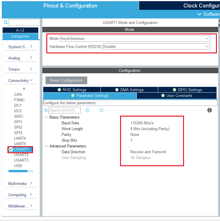
2. Pin configuration
4. Main functions
According to our tutorial STM32CubeIDE can generate the corresponding gpio.c, gpio.h, tim.c and tim.h files. For later transplantation and peripheral module driver, we will place the automatically generated code in the BSP under the project file. folder.
1. User function
Function: PS2_Data_Show
| Function prototype | void PS2_Data_Show(void) |
|---|---|
| Function description | Serial port prints PS controller data |
| Input parameters | None |
| Output parameters | None |
Function: PS2_Data_Show
| Function prototype | uint8_t PS2_DataKey() |
|---|---|
| Function description | Process the read PS2 data, only process the button part |
| Input parameters | None |
| Output parameters | When only one button is pressed, the value is 0, and when it is not pressed, it is 1 |
Function: PS2_ReadData
| Function prototype | void PS2_ReadData(void) |
|---|---|
| Function description | Read controller data |
| Input parameters | None |
| Output parameters | None |
Function: PS2_ClearData
| Function prototype | void PS2_ClearData() |
|---|---|
| Function description | Clear data buffer |
| Input parameters | None |
| Output parameters | None |
Function: PS2_Cmd
| Function prototype | void PS2_Cmd(uint8_t CMD) |
|---|---|
| Function description | Send commands to the controller |
| Input parameters | CMD command |
| Output parameters | None |
5. Experimental phenomena
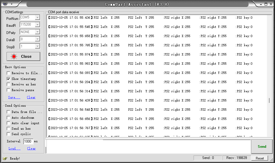
After downloading the program, set the parameters as shown in the figure below, and then open the serial port assistant. At the same time, connect the handle receiver and expansion board wiring. You can receive the controller key value information through the serial port assistant.
xxxxxxxxxxFor program download, please refer to [2. Development environment construction and use: program download and simulation
The effect is as follows: