Welcome to L-Type Motor repository
For MSPM0G3519
Motor drive and encoder reading - IIC
1.1 Introduction
Please read "0.520 motor introduction and usage" first to understand the motor parameters, wiring method, and power supply voltage you are currently using. To avoid burning the motherboard or motor.
I2C and serial port communication cannot be shared, only one can be selected.
The relationship between the 4 motor interfaces and the car is as follows:
M1 -> upper left motor (left front wheel of the car) M2 -> lower left motor (left rear wheel of the car) M3 -> upper right motor (right front wheel of the car) M4 -> lower right motor (right rear wheel of the car)
Hardware wiring:
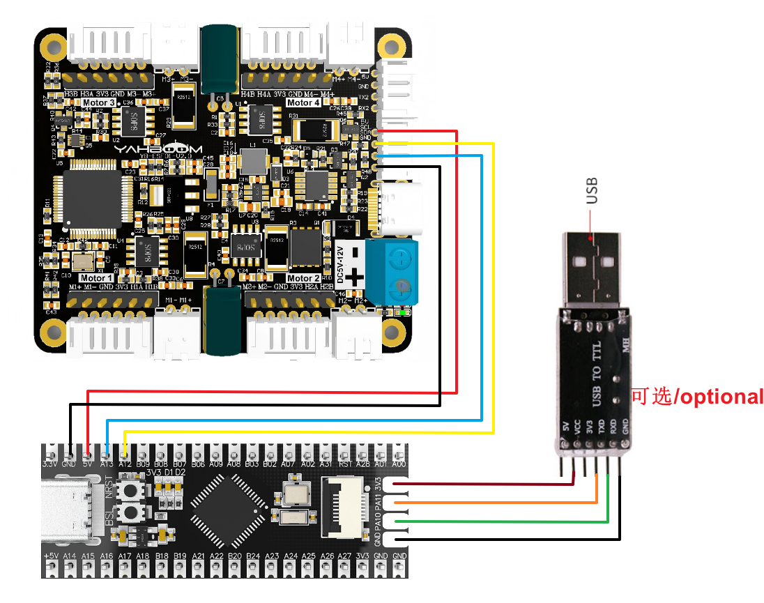
| Four-way motor driver board | MSPM0G3519 |
|---|---|
| SDA | PA13 |
| SCL | PA12 |
| GND | GND |
| 5V | 5V |
| Motor | Four-way motor driver board (Motor) |
|---|---|
| M2 | M- |
| V | 3V3 |
| A | H1B |
| B | H1A |
| G | GND |
| M1 | M+ |
Connect the USB to TTL serial port module here, which is used to print the processed encoder data. If you use the MSPM0G3519 purchased in this store, you can directly connect it to the computer USB port through the TYPE-C interface, and you can also use the serial port to print, so you don’t need to connect the USB to TTL serial port module.
| USB TO TTL | MSPM0G3519 |
|---|---|
| VCC | 3V3 |
| GND | GND |
| RXD | PA10 |
| TXD | PA11 |
Serial port configuration: Baud rate 115200, no parity check, no hardware flow control, 1 stop bit
Note: The serial port here is used to print data on the serial port assistant, not for communication with the driver board
1.2 Code explanation
x// 1: Receive total encoder data 2: Receive real-time encoder data
//1:520 motor 2:310 motor 3:speed code disc TT motor 4:TT DC reduction motor 5:L type 520 motorUPLOAD_DATA: used to set the data of the motor encoder. Set 1 to the total number of encoder pulses and 2 to the real-time pulse data of 10ms.
MOTOR_TYPE: used to set the type of motor used. Just modify the corresponding numbers according to the comments according to the motor you are currently using. You don’t need to modify the rest of the code.
If you need to drive the motor and observe the data, just modify the two numbers at the beginning of the program. No changes are required to the rest of the code.
xxxxxxxxxx Set_motor_type(1);//Configure motor type delay_ms(100); Set_Pluse_Phase(30);//Configure the reduction ratio. Check the motor manual to find out delay_ms(100); Set_Pluse_line(11);//Configure the magnetic ring wire. Check the motor manual to get the result. delay_ms(100); Set_Wheel_dis(67.00);//Configure the wheel diameter and measure it delay_ms(100); Set_motor_deadzone(1900);//Configure the motor dead zone, and the experiment shows delay_ms(100); Set_motor_type(2); delay_ms(100); Set_Pluse_Phase(20); delay_ms(100); Set_Pluse_line(13); delay_ms(100); Set_Wheel_dis(48.00); delay_ms(100); Set_motor_deadzone(1600); delay_ms(100); Set_motor_type(3); delay_ms(100); Set_Pluse_Phase(45); delay_ms(100); Set_Pluse_line(13); delay_ms(100); Set_Wheel_dis(68.00); delay_ms(100); Set_motor_deadzone(1250); delay_ms(100); Set_motor_type(4); delay_ms(100); Set_Pluse_Phase(48); delay_ms(100); Set_motor_deadzone(1000); delay_ms(100); Set_motor_type(1); delay_ms(100); Set_Pluse_Phase(40); delay_ms(100); Set_Pluse_line(11); delay_ms(100); Set_Wheel_dis(67.00); delay_ms(100); Set_motor_deadzone(1900); delay_ms(100);
This is used to store the parameters of the motors sold in our store. By modifying the MOTOR_TYPE parameter above, one-click configuration can be achieved. Under normal circumstances, do not modify the code here when using the motors in our store. If you are using your own motor, or if a certain data needs to be modified according to your needs, you can check the document "4-way motor driver board control instructions" to understand the specific meaning of each instruction.
xxxxxxxxxx while(1) { if(times>=25)//The timer accumulates every 100ms, and when it reaches 25 times, that is, every 2.5 seconds, the state of the car is changed. { Car_Move_PWM(); Car_Move(); times = 0; } Read_ALL_Enconder(); printf("M1:%d\t M2:%d\t M3:%d\t M4:%d\t \r\n",Encoder_Now[0],Encoder_Now[1],Encoder_Now[2],Encoder_Now[3]); Read_10_Enconder(); printf("M1:%d\t M2:%d\t M3:%d\t M4:%d\t \r\n",Encoder_Offset[0],Encoder_Offset[1],Encoder_Offset[2],Encoder_Offset[3]); } }
//The timer's interrupt service function interrupts once every 100msvoid TIMER_0_INST_IRQHandler(void){ //If a timer interrupt occurs switch( DL_TimerG_getPendingInterrupt(TIMER_0_INST) ) { case DL_TIMER_IIDX_ZERO://If it is 0 overflow interrupt times++; break;
default: break; }}
A 100ms timer is set in the program. Each time the timer interrupt is triggered, the times variable will be incremented by one. When it reaches 25 times, that is, 2.5 seconds, the motion state of the car will be changed. If the motor type is 4, that is, the motor without encoder, the pwm version of the car state switching function is used. At the same time, the data sent by the driver board is read and printed out at the same time.
xxxxxxxxxx//Read the data of the encoder of relative time 10msvoid Read_10_Enconder(void){    static int8_t buf[2];            //M1 motor encoder data    i2cRead(Motor_model_ADDR, READ_TEN_M1Enconer_REG, 2, buf);    Encoder_Offset[0] = buf[0]<<8|buf[1];         //M2 motor encoder data    i2cRead(Motor_model_ADDR, READ_TEN_M2Enconer_REG, 2, buf);    Encoder_Offset[1] = buf[0]<<8|buf[1];        //M3 motor encoder data    i2cRead(Motor_model_ADDR, READ_TEN_M3Enconer_REG, 2, buf);    Encoder_Offset[2] = buf[0]<<8|buf[1];        //M4 motor encoder data    i2cRead(Motor_model_ADDR, READ_TEN_M4Enconer_REG, 2, buf);    Encoder_Offset[3] = buf[0]<<8|buf[1];    }
//Read the encoder data of the motor rotationvoid Read_ALL_Enconder(void){    static uint8_t buf[2];    static uint8_t buf2[2];        //M1 motor encoder data    i2cRead(Motor_model_ADDR, READ_ALLHigh_M1_REG, 2, buf);    i2cRead(Motor_model_ADDR, READ_ALLLOW_M1_REG, 2, buf2);        Encoder_Now[0] = buf[0]<<24|buf[1]<<16|buf2[0]<<8|buf2[1];         //M2 motor encoder data    i2cRead(Motor_model_ADDR, READ_ALLHigh_M2_REG, 2, buf);    i2cRead(Motor_model_ADDR, READ_ALLLOW_M2_REG, 2, buf2);    Encoder_Now[1] = buf[0]<<24|buf[1]<<16|buf2[0]<<8|buf2[1];        //M3 motor encoder data    i2cRead(Motor_model_ADDR, READ_ALLHigh_M3_REG, 2, buf);    i2cRead(Motor_model_ADDR, READ_ALLLOW_M3_REG, 2, buf2);    Encoder_Now[2] = buf[0]<<24|buf[1]<<16|buf2[0]<<8|buf2[1];        //M4 motor encoder data    i2cRead(Motor_model_ADDR, READ_ALLHigh_M4_REG, 2, buf);    i2cRead(Motor_model_ADDR, READ_ALLLOW_M4_REG, 2, buf2);    Encoder_Now[3] = buf[0]<<24|buf[1]<<16|buf2[0]<<8|buf2[1];    }
After getting the data from the driver board, shift it. Shifting is required to get the correct data.
1.3 Experimental Phenomenon
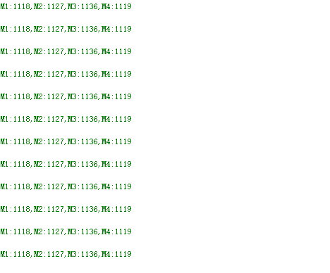
After the wiring is correct, burn the program into the main board. After resetting, you can see that the car will move forward for 2.5 seconds, move back for 2.5 seconds, rotate right for 2.5 seconds, rotate left for 2.5 seconds, then stop for 2.5 seconds, and continue the above state switching actions. At the same time, you can see that the printed motor values are constantly changing in the serial port assistant.